System, method and apparatus for control surface with dynamic compensation

Inactive Publication Date: 2009-12-10
LOCKHEED MARTIN CORP
View PDF54 Cites 16 Cited by
  • Summary
  • Abstract
  • Description
  • Claims
  • Application Information

AI Technical Summary

Benefits of technology

[0006]Embodiments of a system, method, and apparatus for active manipulation of the stiffness of a control surface and a control surface actuator are disclosed. The manipulation may be accomplished both proactively and reactively. The control surface is coupled to one or more sensors and actuators so that the actuators can respond to sensed conditions. The control surface is further coupled to an overall flight control system of the aircraft so that the actuator can respond proactively to planned or anticipated maneuvers of the control surface. The invention does not replace the actuator but assists and enables it to meet selected design requirements. The invention allows actuator power capacity to be reduced to match maneuver force requirements, rather than being designed for stiffness. The invention also alleviates complexity within the actuator design.
[0007]By reducing the moveable control surface actuator's power capacity, the weight and size requirements of the actuator are reduced. The entire control surface actuator system may have more complexity due to the addition of the invention, however, the reduction in actuator weight and complexity offsets the additions to the overall system. The device may be used to provide stiffness similar to a hydraulically pressurized actuator, but the device is easier to use, modify and service (e.g., remove and replace) because it is a sealed unit and has no plumbing connections. As an added benefit, the device and the actuator may be complementary for automated built-in-testing (BIT) of each other for proper operation prior to each flight of the aircraft.
[0008]In some embodiments, the invention uses an active mechanical damping device that incorporates magneto-rheological (MR) technology. The device has a valve through which an MR fluid is selectively manipulated based on the properties of the fluid. A magnetic field is applied and limited to only the area of the valve orifice through which the MR fluid flows. The magnetic field, which is adjustable, variably changes the local flow rate of the fluid through the orifice which, in turn, regulates the motion of the control surface. Thus, the invention is active with regard to the damping effect, but is passive with regard to its power consumption to move the control surfaces being manipulated. The device provides a control surface and structure stiffening effect at frequencies that are critical for structural dynamics stiffness requirements. The device also acts as a back-up system to the actuator in the event of actuator failure, by facilitating a fail-safe operation, thereby reducing complexity of the actuator redundant design.

Problems solved by technology

This requirement makes the size of the actuator and its mechanical complexity significantly greater than what is required for non-redundant maneuver design load capacity.

Method used


Image

  • System, method and apparatus for control surface with dynamic compensation
  • System, method and apparatus for control surface with dynamic compensation
  • System, method and apparatus for control surface with dynamic compensation

Examples


Embodiment Construction

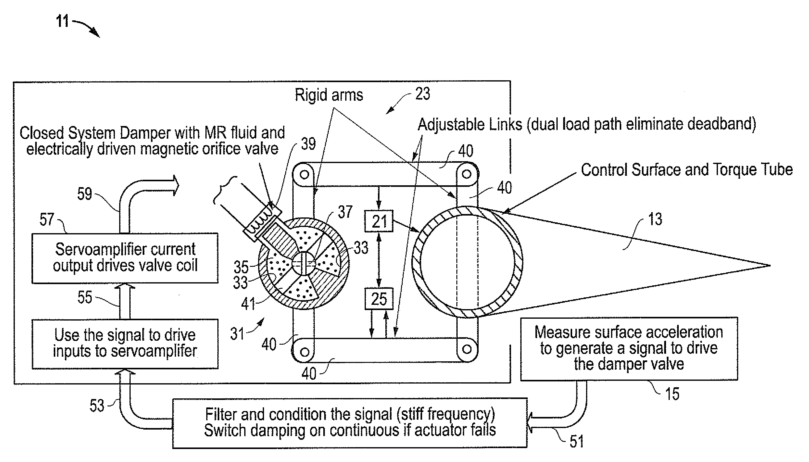
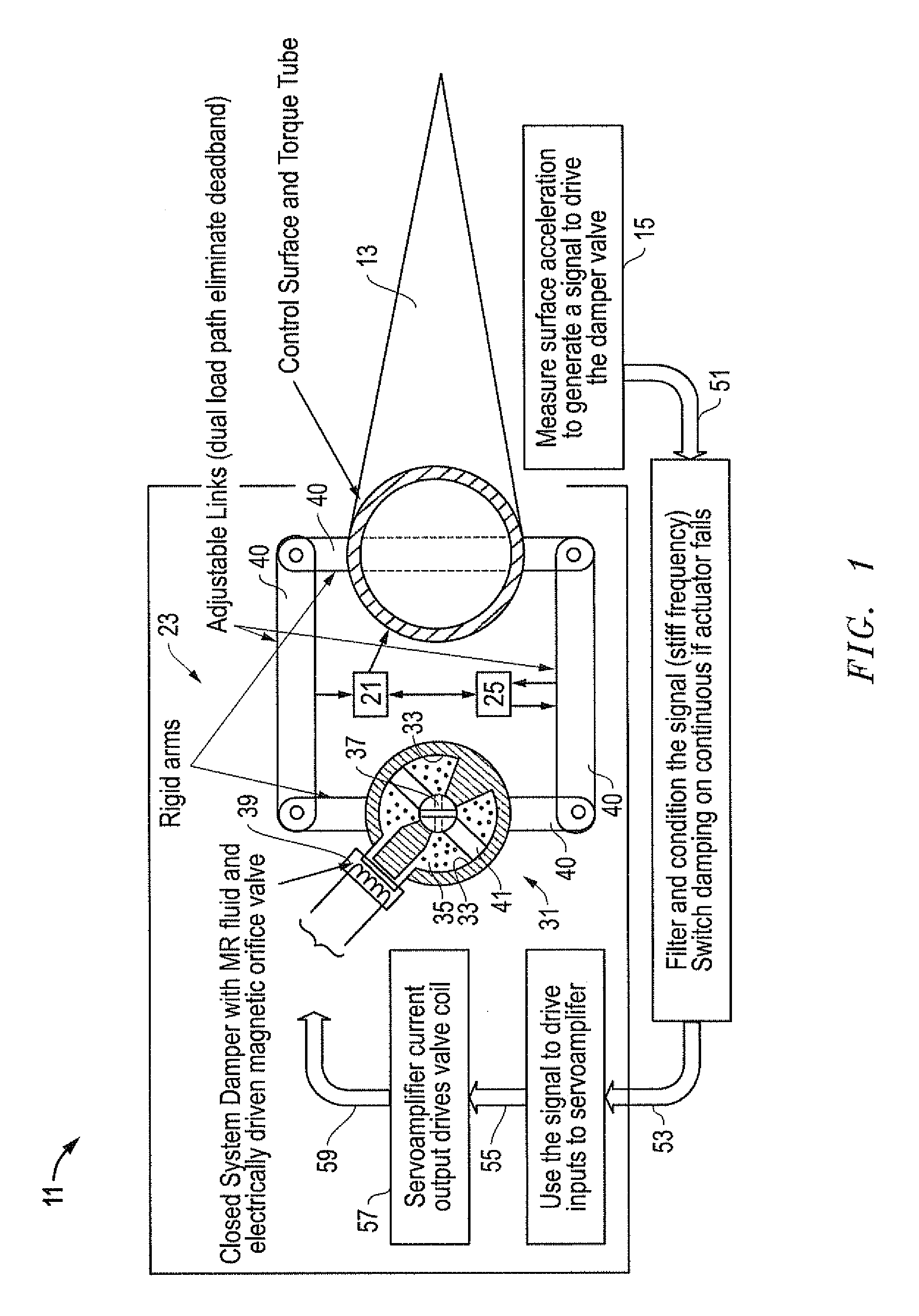
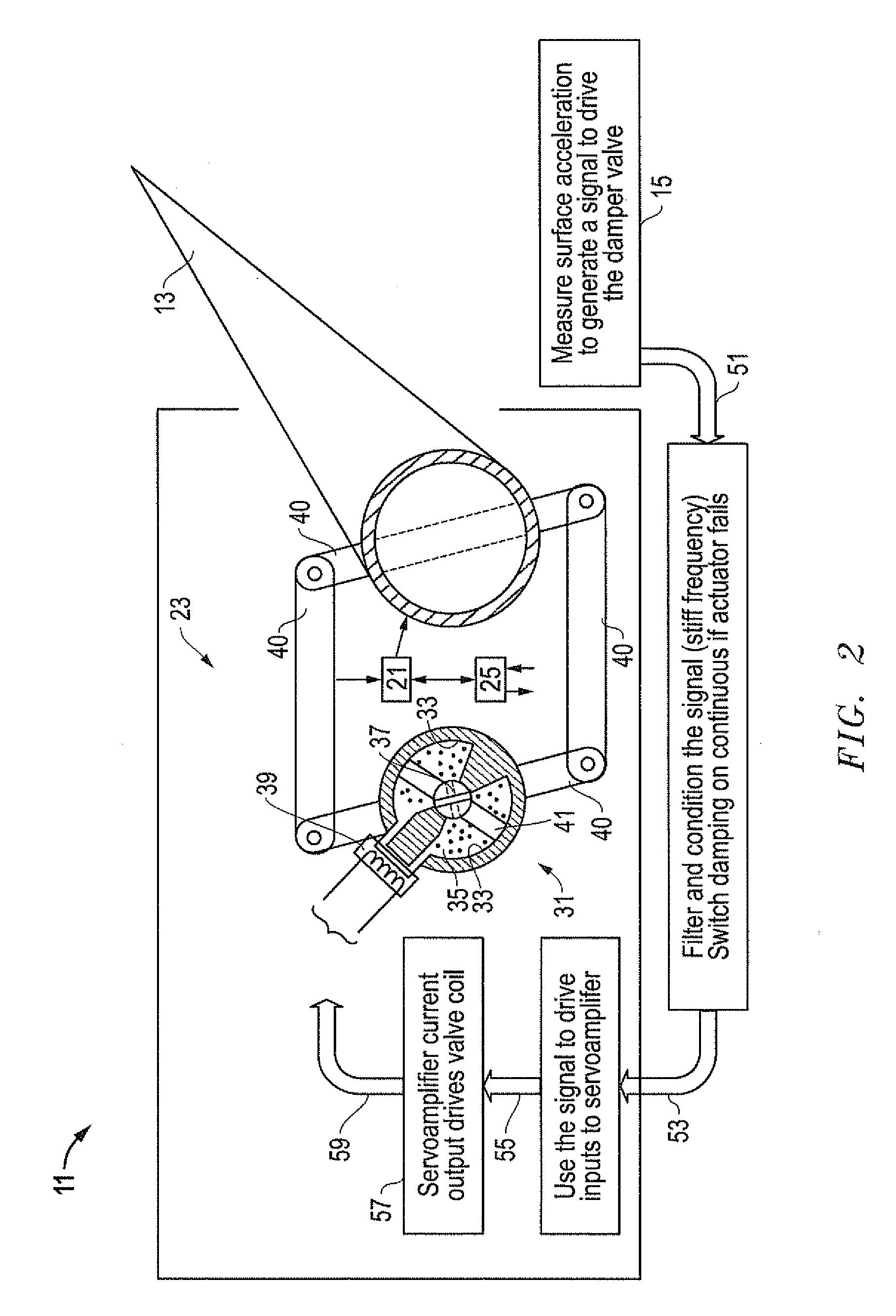
[0013]Referring to FIGS. 1-4, embodiments of a system, method and apparatus for an aircraft flight control surface having a dynamic compensation capacity for both reactively and proactively manipulating the control surface. The invention is well suited for controlling and manipulating a flight control device or “flap” of an aircraft, such as a rudder, an aileron, an elevator, etc., as is known in the art.

[0014]The aircraft is schematically indicated in FIG. 1 as having a body 11 with wings and tail components. A flight control device or flap 13 is movably mounted to the body 11 for adjusting flight of the aircraft during operation. A sensor 15 is mounted to the body 11 for detecting a movement (e.g., acceleration) of the flap 13 as it is operated. The flap 13 may be controlled with a single manipulation device 21 or a plurality of manipulation devices 21, 23 (see, e.g., FIG. 4) for redundancy and additional safety. For example, a “primary” manipulation device 21 may used for primari...


PUM


Abstract

An aircraft flight control surface has an actuator that employs a magneto-rheological (MR) fluid for dynamically adjusting the responsiveness of the control surface. The MR fluid may be used as a primary or secondary control in the event that a primary control actuator fails. In the event of system failures associated with the primary control, an alternate level of performance may be provided by the secondary control and communicated to the overall flight control system. This permits the control surface actuator to reactively and proactively respond to changes associated with the flight control system. If the design fails, it also permits a safe mode of operation should the ability to dynamically adjust the viscosity of the MR fluid be negatively impacted. The safe mode of operation may involve a reduced level of performance.

Description

BACKGROUND OF THE INVENTION[0001]1. Technical Field[0002]The present invention relates in general to dynamic manipulation of control surfaces and, in particular, to an improved system, method and apparatus for an aircraft flight control surface having a dynamic compensation capacity for both reactively and proactively manipulating the control surface.[0003]2. Description of the Related Art[0004]In the prior art, the control surfaces of aircraft (e.g., rudders, ailerons, etc.; sometimes referred to as “flaps”) are manipulated by mechanical actuators that selectively move the control surfaces in response to the overall flight control system of the aircraft. The size of the actuator typically is determined by stiffness requirements of the control surface. The stiffness requirements for structural dynamics usually require the size of the actuator to be greater than what is required for maneuver design load capacity.[0005]In the event of actuator failure, there also is a redundancy requi...

Claims


Application Information

Patent Timeline
IPC IPC(8): F16F9/53F16F15/03
CPCY02T50/44B64C13/46B64C13/341B64C13/504B64C13/505B64C13/507Y02T50/40
Inventor STEELE, JEAN P.
Owner LOCKHEED MARTIN CORP
Why Eureka
Try Eureka