
Rotatable inputting apparatus

Inactive Publication Date: 2009-12-10
SAMSUNG ELECTRO MECHANICS CO LTD
View PDF4 Cites 8 Cited by
  • Summary
  • Abstract
  • Description
  • Claims
  • Application Information

AI Technical Summary

Benefits of technology

[0014]The present invention has been made in an effort to provide a rotatable inputting apparatus, which is provided with a connecting guide, thus allowing the reference position of the rotatable inputting apparatus to be easily set, and allowing a circuit board of the rotatable inputting apparatus to be easily coupled to a main circuit board of an objective product, when the rotatable inputting apparatus is placed and mounted on the main circuit board of the objective product such as a remote control or a mobile phone, therefore reducing the number of assembly processes and the assembly period.

Problems solved by technology

However, the conventional rotatable inputting apparatus constructed as described above is problematic in that holes must be bored through both sides of the circuit board of the rotatable inputting apparatus, and the circuit board must be assembled with a main circuit board of an objective product using screws, so as to precisely place and mount the inputting apparatus on the main circuit board of the objective product, such as a remote control or a mobile phone, so that the number of assembly processes is increased.
Further, the conventional rotatable inputting apparatus is problematic in that, when the rotatable inputting apparatus is placed on the main circuit board of the objective product, it is difficult to set the reference position of the rotatable inputting apparatus, so that the assembly period is relatively long.

Method used


Image

  • Rotatable inputting apparatus
  • Rotatable inputting apparatus
  • Rotatable inputting apparatus

Examples


Embodiment Construction

[0026]Hereinafter, a rotatable inputting apparatus according to the preferred embodiment of the present invention will be described in detail with reference to the accompanying drawings.

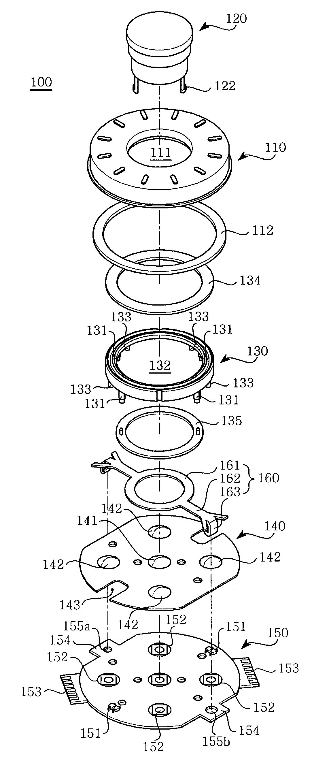
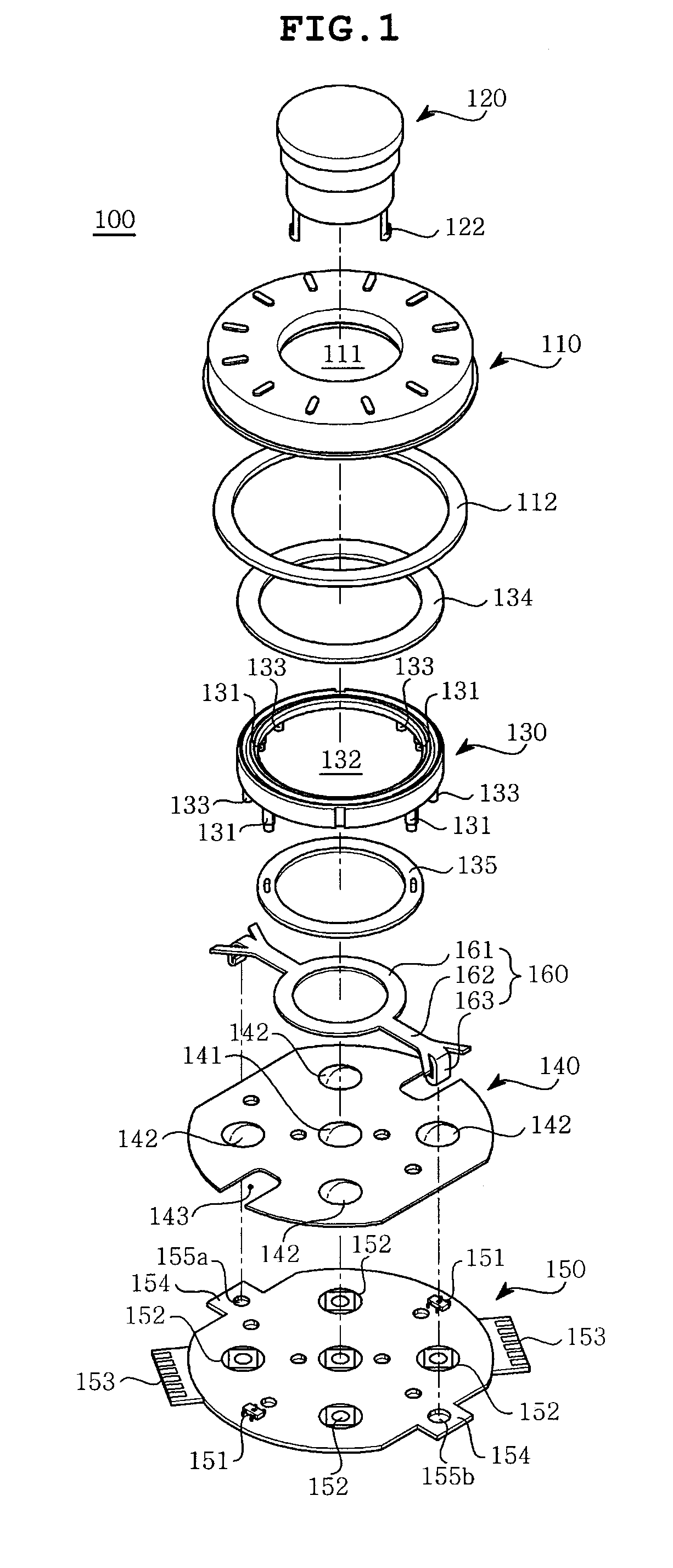
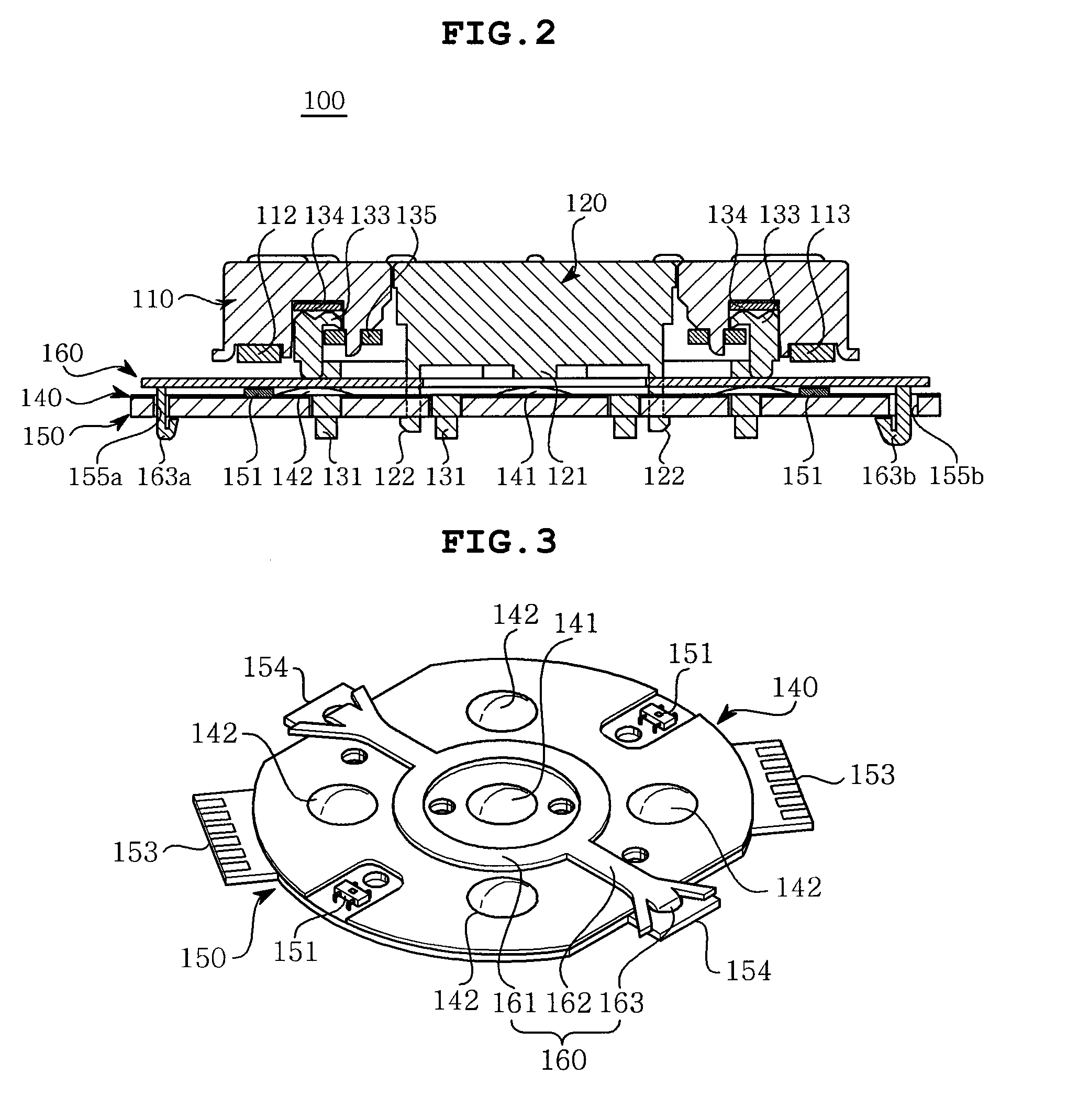
[0027]As shown in FIGS. 1 and 2, a rotatable inputting apparatus 100 according to the embodiment of the present invention includes a wheel 110, a center key 120, a support holder 130, a dome seat 140, a circuit board 150 and a connecting guide 160.

[0028]The wheel 110 is manipulated directly by a user to be rotated in a forward or backward direction. A center hole 111 is bored through the central portion of the wheel 110, and a multi-pole ring magnet 112 is provided along the edge of the bottom of the wheel 110. The wheel 110 is rotatably supported by the support holder 130.

[0029]As shown in FIG. 2, the wheel 110 is manufactured to have the shape of a disc having a predetermined thickness. An annular groove 113 is formed at a position adjacent to the lower edge of the wheel 110 in such a way as to be ...


PUM


Abstract

Disclosed herein is a rotatable inputting apparatus. When a circuit board of the rotatable inputting apparatus is coupled to a main circuit board of a terminal or remote control, the rotatable inputting apparatus of the invention allows reference points of the boards to be instinctively recognized without the necessity of forming reference projections or using screws, thus enabling its easy assembly. The rotatable inputting apparatus includes a wheel having a ring magnet, a support having a pressure pin, a center key moving in a vertical direction, a dome seat including a central dome button and peripheral dome buttons, a circuit board to which the dome seat is attached, and a connecting guide which is secured to the circuit board and has a connecting part. The connecting part passes through the circuit board and is inserted into the main circuit board.

Description

CROSS REFERENCE TO RELATED APPLICATION(S)[0001]This application claims the benefit of Korean Patent Application No. 10-2008-0053637, filed on Jun. 9, 2008, entitled “rotatable inputting apparatus”, which is hereby incorporated by reference in its entirety into this application.BACKGROUND OF THE INVENTION[0002]1. Field of the Invention[0003]The present invention relates generally to a rotatable inputting apparatus which is mounted to a terminal, such as a mobile communication terminal or a PDA, or a remote control and, more particularly, to a rotatable inputting apparatus which can be coupled to a main circuit board of a terminal or remote control while reference points are instinctively recognized without the necessity of forming reference projections or using screws, when a circuit board of the rotatable inputting apparatus having a dome-shaped switch, a wheel, and other parts is coupled to the main circuit board, thus enabling its easy assembly.[0004]2. Description of the Related ...

Claims


Application Information

Patent Timeline
IPC IPC(8): H01H13/72
CPCG06F3/0338G06F3/0362H01H1/5805H01H2025/048H01H19/005H01H25/041H01H2025/043H01H9/0214
Inventor KANG, EUNG CHEON
Owner SAMSUNG ELECTRO MECHANICS CO LTD
Learn More