
Automobile Gear Shifter Kit

a gear shifter and kit technology, applied in the field of automobile components, can solve the problems of preventing the proper gripping of the conventional gear shifter shaft, operator inconvenience in locating a particular switch, and operator discomfort in gripping, so as to achieve the effect of convenient performing desired functions

Inactive Publication Date: 2009-12-10
SMITH TIMOTHY
View PDF15 Cites 1 Cited by
  • Summary
  • Abstract
  • Description
  • Claims
  • Application Information

AI Technical Summary

Benefits of technology

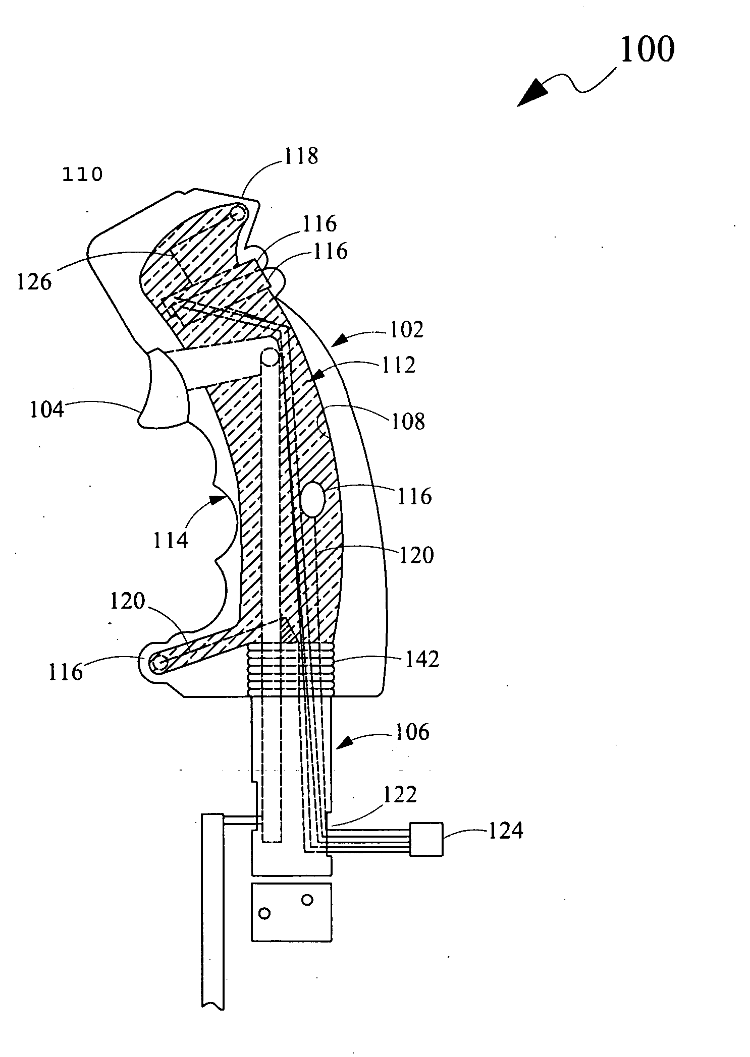
[0008]Another object of the present disclosure is to enable an operator to easily locate switches.
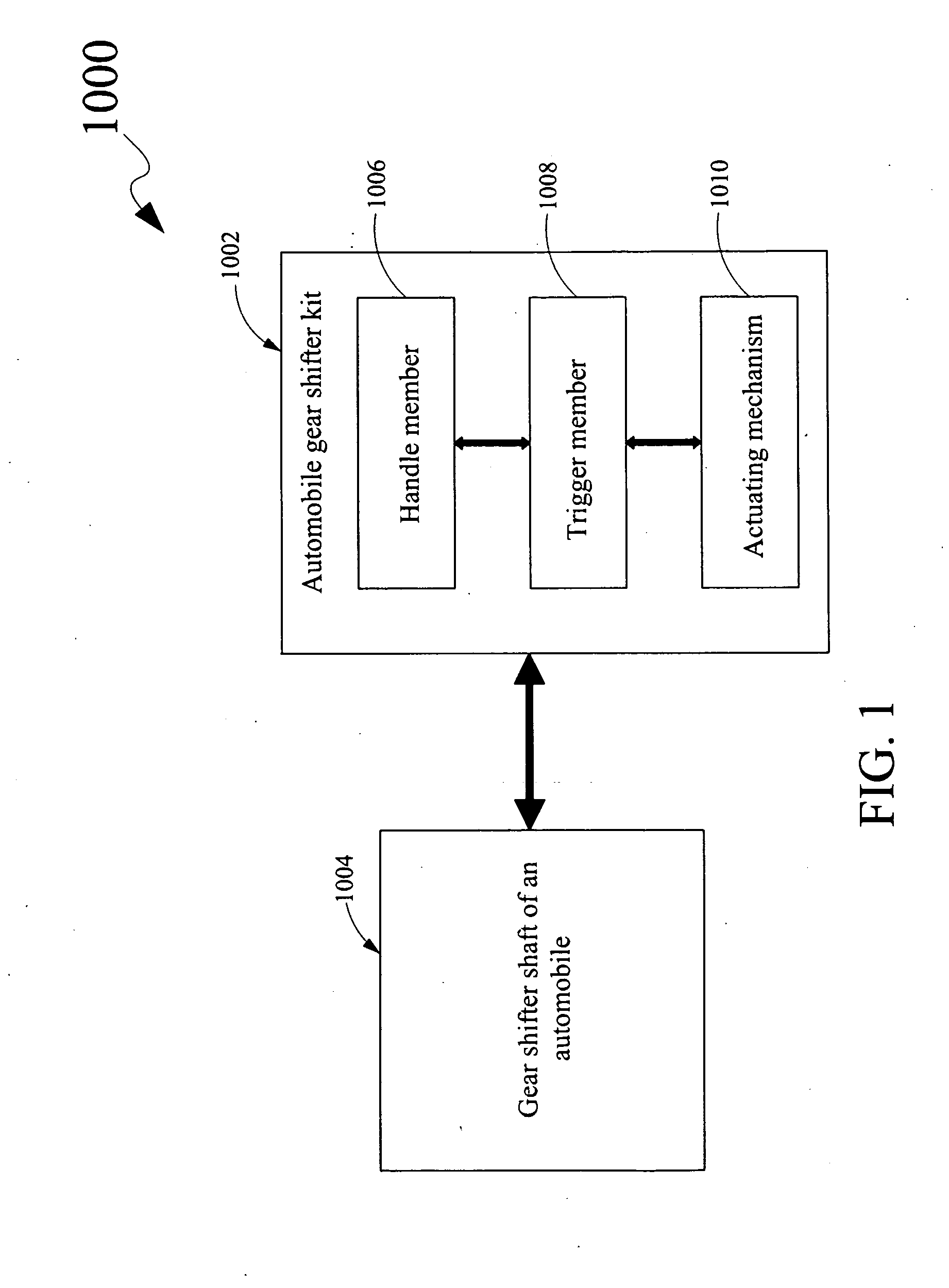
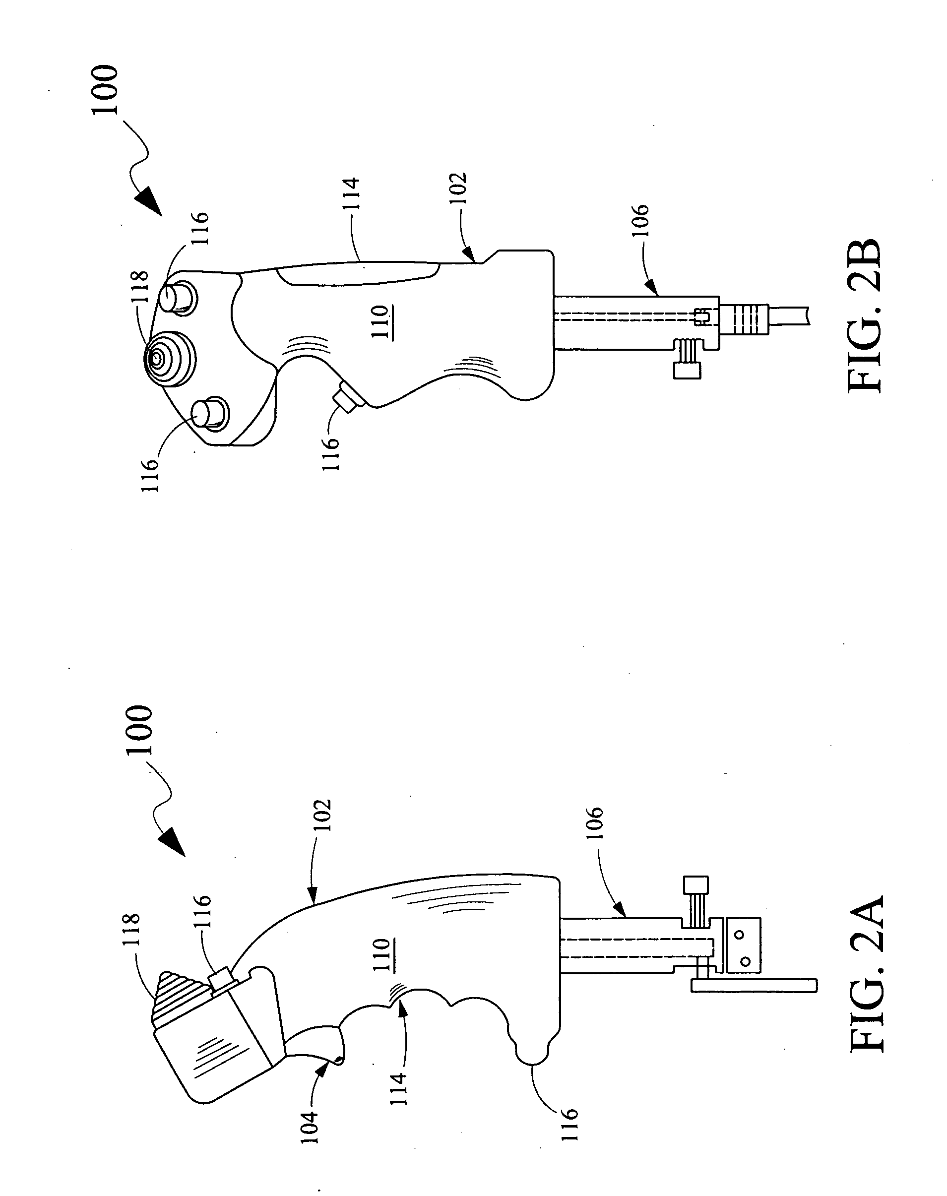
[0013]The pilot control grip, of the automobile gear shifter kit, provided by the outer surface of the handle member facilitates an operator of an automobile to maneuver the handle member in a convenient manner, thereby precluding inconvenience to an operator while changing gears for providing transmission to the automobile. Further, the automobile gear shifter kit provides the trigger member operatively coupled to the actuating mechanism for facilitating the operator of the automobile for triggering actuation of the actuating mechanism for actuating the at least one of the shifting of the gears of the automobile and the operation of pre-determined auxiliary function, thereby enabling the operator to easily perform desired functions in the automobile.

Problems solved by technology

However, conventional knob assemblies include various problems that preclude a proper gripping of the conventional gear shifter shaft.
For example, structures and ergonomics of the conventional knob assemblies are such that the operator may feel inconvenience in the gripping thereof while maneuvering the conventional knob assemblies for changing the gears to provide transmission to the automobile.
While driving, the operator may be inconvenienced in locating a particular switch from the various locations of the automobile for a particular auxiliary function.

Method used


Image

  • Automobile Gear Shifter Kit
  • Automobile Gear Shifter Kit
  • Automobile Gear Shifter Kit

Examples


Embodiment Construction

[0026]For a thorough understanding of the present disclosure, reference is to be made to the following detailed description, including the appended claims, in connection with the above-described drawings. Although the present disclosure is described in connection with exemplary embodiments, the present disclosure is not intended to be limited to the specific forms set forth herein. It is understood that various omissions and substitutions of equivalents are contemplated as circumstances may suggest or render expedient, but these are intended to cover the application or implementation without departing from the spirit or scope of the claims of the present disclosure. Also, it is to be understood that the phraseology and terminology used herein is for the purpose of description and should not be regarded as limiting. The use of “including,”“comprising,” or “having” and variations thereof herein is meant to encompass the items listed thereafter and equivalents thereof as well as additi...


PUM


Abstract

An automobile gear shifter kit includes a handle member, a trigger member and an actuating mechanism. The handle member is capable of being removably coupled to a gear shifter shaft of an automobile. The handle member includes an inner surface and an outer surface. The inner surface is configured to define a cavity portion and the outer surface is configured to provide a pilot control grip. The trigger member is disposed on the outer surface and is capable of triggering actuation of at least one of shifting of gears of the automobile and an operation of pre-determined auxiliary function of the automobile. The actuating mechanism is disposed in the cavity portion and is operatively coupled to the trigger member for being triggered by the trigger member for actuating the at least one of the shifting of the gears of the automobile and the operation of pre-determined auxiliary function.

Description

CROSS-REFERENCE TO RELATED APPLICATIONS[0001]The present disclosure claims priority under 35 United States Code, Section 119 on the U.S. Provisional Patent Application No. 61 / 130,936 filed on Jun. 4, 2008, the disclosure of which is incorporated by reference.FIELD OF THE DISCLOSURE[0002]The present disclosure relates, in general, to automobile components, and more particularly to an automobile gear shifter kit for an automobile.BACKGROUND OF THE DISCLOSURE[0003]Gear shifter arrangements typically include gear shifter shafts coupled to standard components of an automobile with a manual or an automatic transmission. A conventional gear shifter shaft includes a knob assembly for facilitating in gripping the conventional gear shifter shaft to enable an operator of the automobile to change gears of the automobile's transmission. However, conventional knob assemblies include various problems that preclude a proper gripping of the conventional gear shifter shaft. For example, structures an...

Claims


Application Information

Patent Timeline
IPC IPC(8): F16H59/04B60K20/00
CPCF16H59/04Y10T74/2003Y10T74/2014F16H59/0278
Inventor SMITH, TIMOTHY
Owner SMITH TIMOTHY
Learn More