
Reduced-pressure, compression systems and apparatuses for use on a curved body part

a compression system and curved body technology, applied in the field of medical treatment systems, can solve the problems of a number of potential problems, damaged tissue will need time and care to heal, and achieve the effect of reducing pressur

Active Publication Date: 2009-12-03
KCI LICENSING INC
View PDF100 Cites 87 Cited by
  • Summary
  • Abstract
  • Description
  • Claims
  • Application Information

AI Technical Summary

Benefits of technology

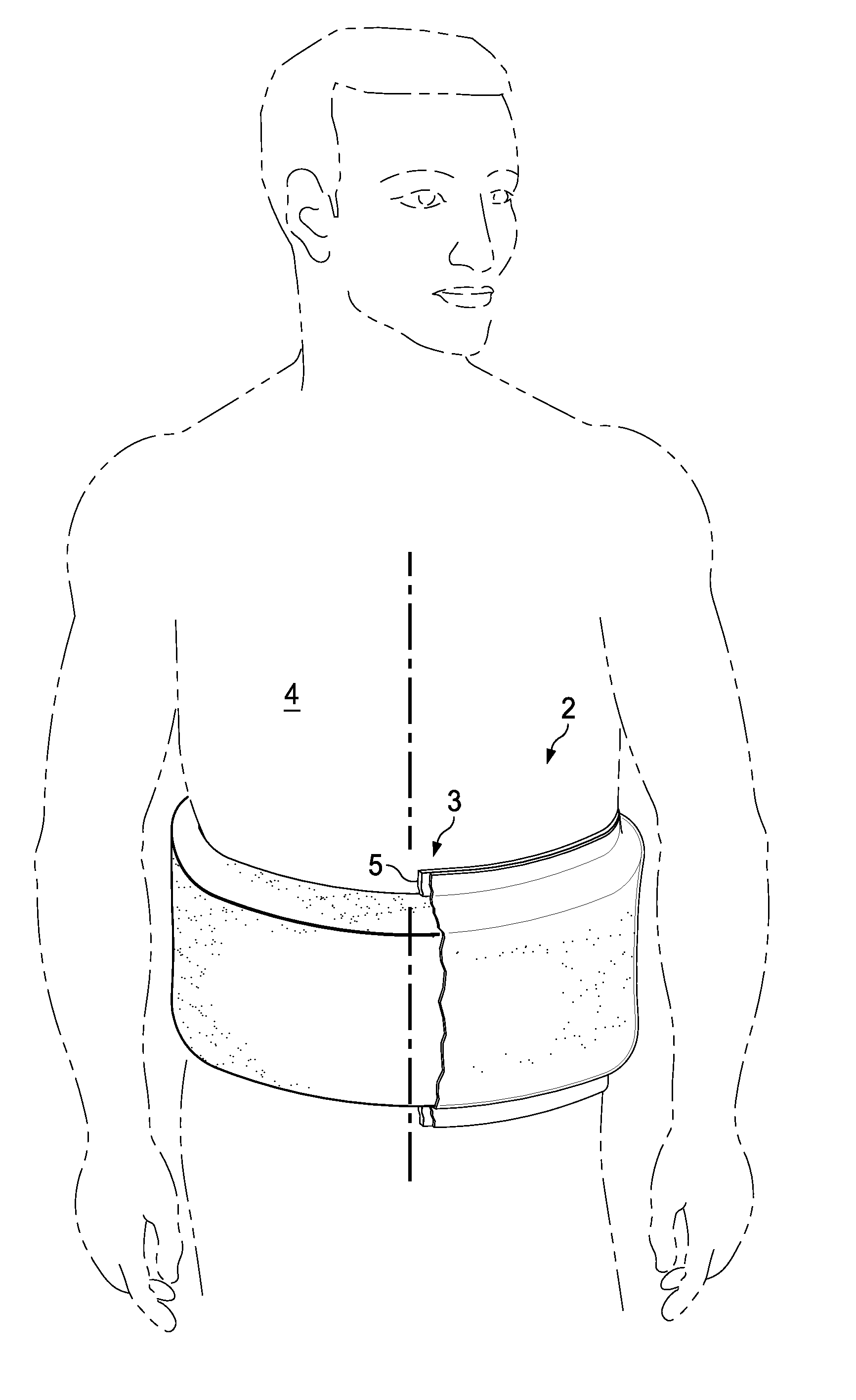
[0011]According to one illustrative embodiment, a method of providing a force to at least a portion of a curved body part of a person includes the steps of: deploying a dressing assembly on the curved body part. The dressing assembly includes an interior surface member for placing over the desired treatment area and having a first surface and a second, inward-facing surface and a dressing bolster having a first surface and a second, inward-facing surface. The second, inward-facing surface of the dressing bolster is disposed against the first surface of the interior surface member thereby sealing the dressing assembly to the curved body part. The method further includes providing reduced pressure to the dressing assembly. The dressing bolster has a first volume (V1) at ambient pressure and a second volume (V2) when under reduced pressure and V1>V2.

Problems solved by technology

The damaged tissue will need time and care to heal and poses a number of potential complications and risks including edema, seroma, hematoma, further bruising, and ecchymosis to name some.

Method used


Image

  • Reduced-pressure, compression systems and apparatuses for use on a curved body part
  • Reduced-pressure, compression systems and apparatuses for use on a curved body part
  • Reduced-pressure, compression systems and apparatuses for use on a curved body part

Examples


Embodiment Construction

[0029]In the following detailed description of illustrative embodiments, reference is made to the accompanying drawings that form a part hereof, and in which is shown, by way of illustration, specific embodiments in which the invention may be practiced. These embodiments are described in sufficient detail to enable those skilled in the art to practice the invention, and it is understood that other embodiments may be utilized and that logical structural, mechanical, electrical, and chemical changes may be made without departing from the spirit or scope of the invention. To avoid detail not necessary to enable those skilled in the art to practice the invention, the description may omit certain information known to those skilled in the art. The following detailed description is, therefore, not to be taken in a limiting sense, and the scope of the present invention is defined only by the appended claims.

[0030]Referring to FIG. 1, a system 2 for providing a force to a desired treatment a...


PUM

PropertyMeasurementUnit
Densityaaaaaaaaaa
Pressureaaaaaaaaaa
Densityaaaaaaaaaa

Abstract

A system for providing a force to a desired area on a curved body part of a person includes a dressing assembly shaped and configured to be placed on the desired area of the person, a releaseable circumferential member surrounding the curved body part that holds the dressing assembly against the desired area, a sealing subsystem for providing a fluid seal over the dressing assembly and the person's skin, and a reduced-pressure subsystem for providing a reduced pressure to the dressing assembly. When reduced pressure is supplied, the system generates the force against the desired area on the curved body part.

Description

RELATED APPLICATIONS[0001]The present invention claims the benefit, under 35 USC § 119(e), of the filing of U.S. Provisional Patent Application Ser. No. 61 / 057,807, entitled “Reduced-pressure Surgical Wound Treatment System,” filed May 30, 2008; U.S. Provisional Patent Application Ser. No. 61 / 057,798, entitled “Dressing Assembly For Subcutaneous Wound treatment Using Reduce Pressure,” filed May 30, 2008; U.S. Provisional Patent Application Ser. No. 61 / 057,808, entitled “See-Through, Reduced-Pressure Dressing,” filed May 30, 2008; U.S. Provisional Patent Application Ser. No. 61 / 057,802, entitled “Reduced-Pressure Dressing Assembly For Use in Applying a Closing Force,” filed May 30, 2008; U.S. Provisional Patent Application Ser. No. 61 / 057, 803, entitled “Reduced-Pressure, Linear-Wound Treatment System,” filed May 30, 2008; U.S. Provisional Patent Application Ser. No. 61 / 057,800, entitled “Reduced-Pressure, Compression System and Apparatus for use on a Curved Body Part,” filed May 30,...

Claims


Application Information

Patent Timeline
IPC IPC(8): A61F13/00A61F13/14
CPCA61L15/60Y10T29/49826A61M1/0088A61F13/00068A61F13/022A61F13/0223A61F13/0243A61F2013/00174A61F2013/00536A61F2013/0054A61F2013/00748A61F13/0209A61F13/0216A61H1/008A61F13/0289A61F13/00038A61F2013/00131A61F2013/0028A61F13/00029A61F13/00034Y10T29/49A61M1/0023A61M1/916A61M1/71A61M1/915A61F13/05A61M2210/1007A61M2210/1021A61F13/00A61F15/008A61M1/917A61F13/01017A61F13/01029A61F13/01034A61F13/01038A61F2013/00182A61M2207/00A61F2013/00136A61F13/00059A61M2205/70A61F2013/00246
Inventor WILKES, ROBERT PEYTONLONG, JUSTIN ALEXANDERKAZALA, JR., RICHARD MARVIN
Owner KCI LICENSING INC
Learn More