Acoustic treatment apparatus and method thereof
a treatment apparatus and acoustic technology, applied in the direction of speech recognition, direction finders, speech analysis, etc., can solve the problems of deteriorating performance in sound direction estimation and sound source separation, difficult to keep the same sensitivities all the time,
- Summary
- Abstract
- Description
- Claims
- Application Information
AI Technical Summary
Benefits of technology
Problems solved by technology
Method used
Image
Examples
first embodiment
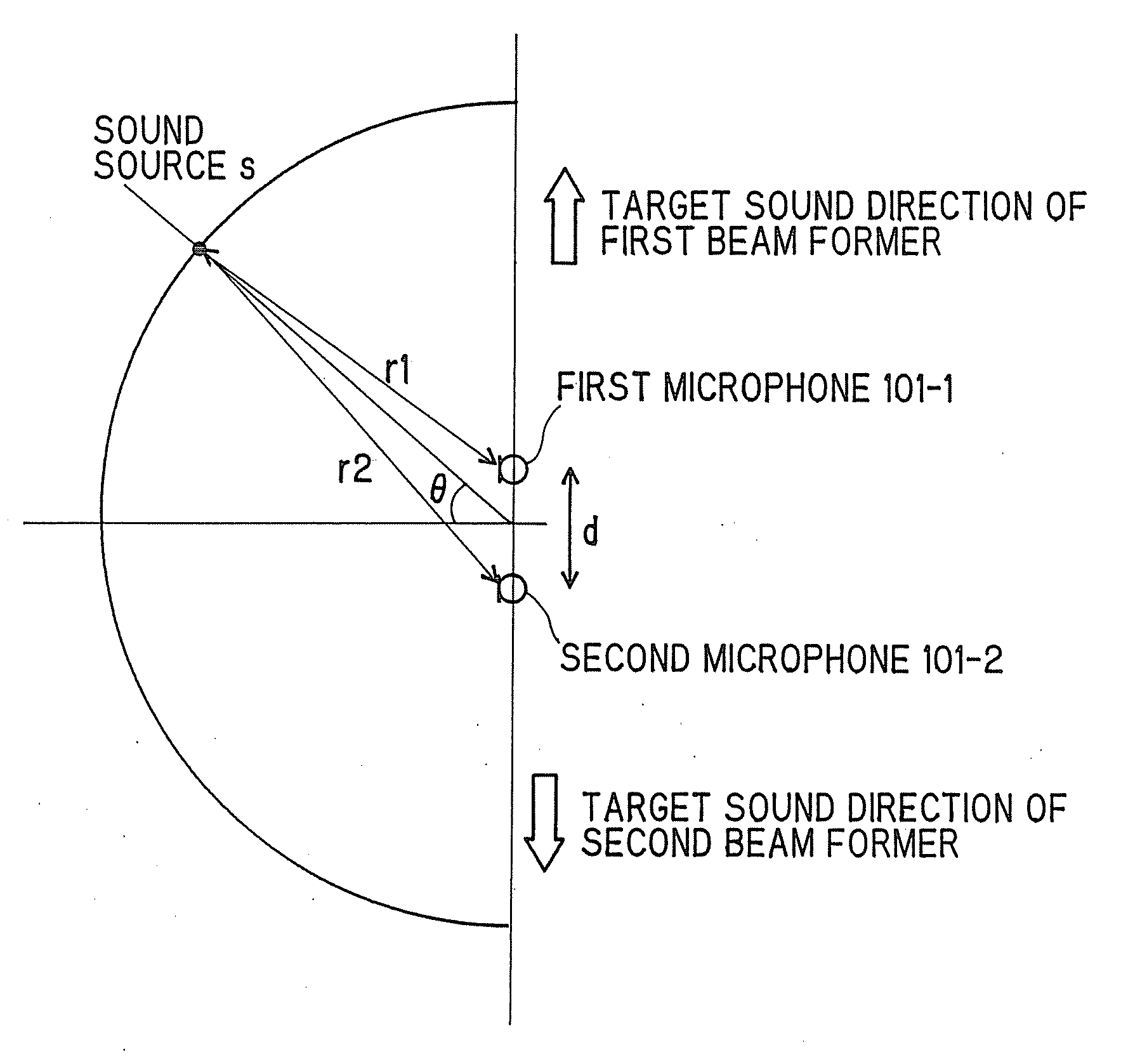
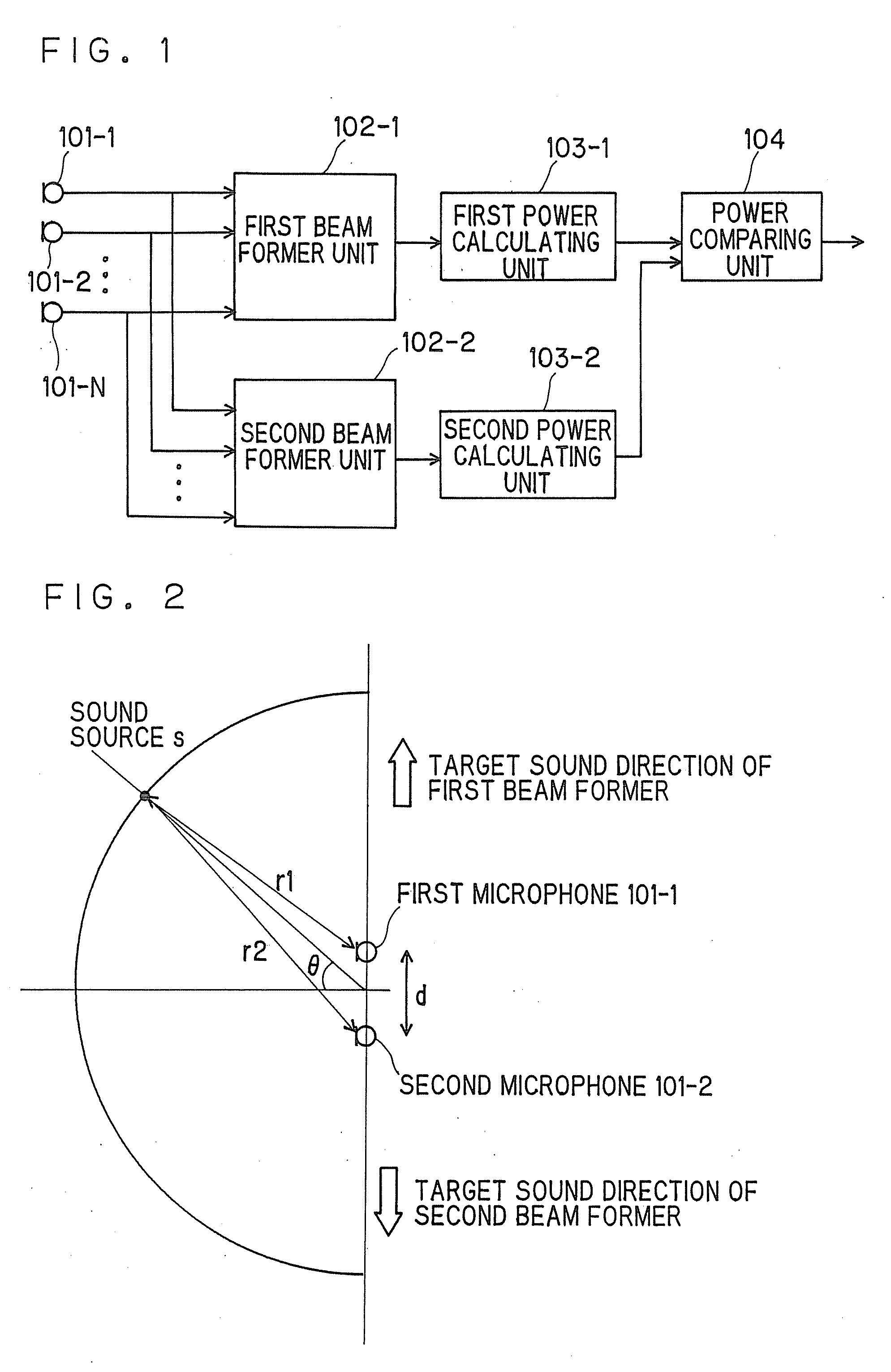
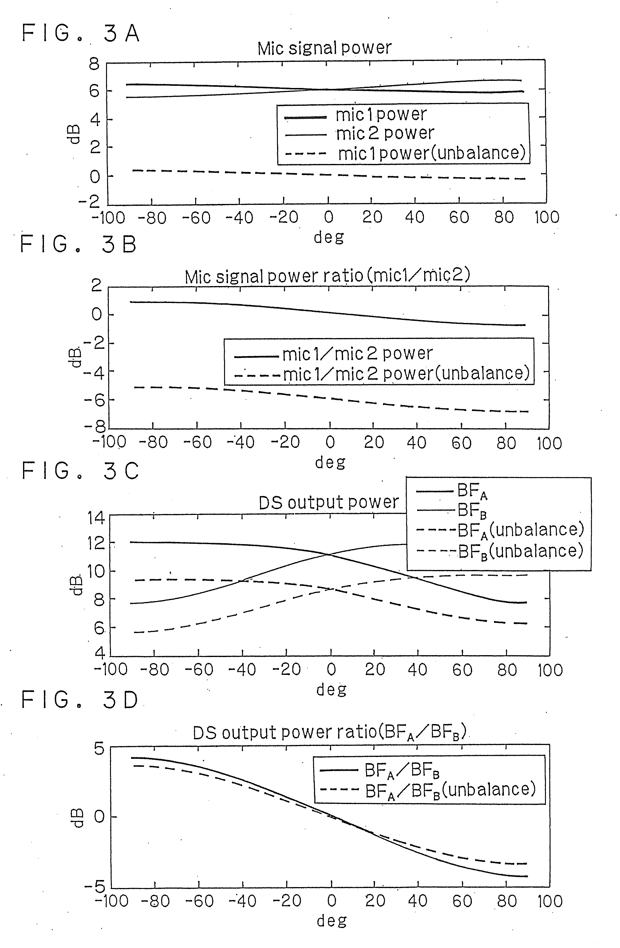
[0019]Referring now to FIG. 1 to FIG. 3, the acoustic treatment apparatus according to the first embodiment will be described.
[0020]FIG. 1 is a block diagram showing an acoustic treatment apparatus according to the first embodiment.
[0021]The acoustic treatment apparatus includes N pieces of sound receivers 101-1 to 101-N, a first beam former unit 102-1 and a second beam former unit 102-2 configured to emphasize and output signals coming from a specific direction by filtering received sound signals, a first power calculating unit 103-1 and a second power calculating unit 103-2 configured to calculate powers as strengths of the output signals, and a power comparing unit 104 configured to obtain ratios of the powers calculated thereby.
[0022]The first beam former unit 102-1, the second beam former unit 102-2, the first power calculating unit 103-1, the second power calculating unit 103-2, and the power comparing unit 104 are implemented by computer readable programs stored or transmitte...
second embodiment
[0055]Referring now to FIG. 4, the acoustic treatment apparatus according to a second embodiment will be described.
[0056]FIG. 4 is a block diagram showing the acoustic treatment apparatus according to the second embodiment.
[0057]According to the second embodiment, a sound source direction estimating unit 105 and a direction data dictionary 106 are provided in addition to the acoustic treatment apparatus in the first embodiment.
[0058]A principle of operation of the acoustic treatment apparatus according to the second embodiment will be described.
[0059]The procedure until the output of the power comparing unit 104 is obtained is the same as in the first embodiment, the description will be omitted.
[0060]The sound source direction estimating unit 105 estimates the sound source direction on the basis of the beam former output ratio obtained by the power comparing unit 104 and data in the direction data dictionary 106.
[0061]More specifically, a correspondence table of the directions of th...
third embodiment
[0067]Referring now to FIG. 4, the acoustic treatment apparatus according to a third embodiment will be described.
[0068]FIG. 5 is a block diagram of the acoustic treatment apparatus according to the third embodiment.
[0069]The acoustic treatment apparatus in the third embodiment includes the sound receivers 101-1 to 101-N, a time frequency transforming unit 208, a frequency component selecting unit 209, a first beam former unit 202-1 and a second beam former unit 202-2 configured to emphasize and output signals coming from a specific direction by filtering the received sound signals for the individual frequency components, a first power calculating unit 203-1 and a second power calculating unit 203-2 configured to calculate the powers of the output signals for the individual frequency components, a power comparing unit 204 configured to obtain the ratios for the individual frequency components, a sound source direction estimating unit 205 configured to estimate the directions of the ...
PUM
 Abstract
Description
Claims
Application Information
 - R&D
- Intellectual Property
- Life Sciences
- Materials
- Tech Scout
- Unparalleled Data Quality
- Higher Quality Content
- 60% Fewer Hallucinations
Browse by: Latest US Patents, China's latest patents, Technical Efficacy Thesaurus, Application Domain, Technology Topic, Popular Technical Reports.
© 2025 PatSnap. All rights reserved.Legal|Privacy policy|Modern Slavery Act Transparency Statement|Sitemap|About US| Contact US: help@patsnap.com


