
Vehicle power supply device

a power supply device and vehicle technology, applied in electric devices, battery/fuel cell control arrangements, instruments, etc., can solve the problems of complex power supply circuit and difficulty in accurately detecting current by current sensors, and achieve the effect of simple configuration and accurate detection of current of high-voltage battery portions

Inactive Publication Date: 2009-12-03
SANYO ELECTRIC CO LTD
View PDF13 Cites 18 Cited by
  • Summary
  • Abstract
  • Description
  • Claims
  • Application Information

AI Technical Summary

Benefits of technology

The present invention provides a vehicle power supply device that can detect both the voltage and current of a high-voltage battery portion using an insulated-type power supply circuit that is simple and can accurately detect the current. This device can be used in vehicles that use a high-voltage battery to power the vehicle. The device includes a current detecting portion and a voltage detecting circuit that work together to accurately detect the current and voltage of the battery. This simplifies the circuit configuration of the device and ensures accurate detection of the current. The high-voltage battery portion can be insulated from the chassis ground, and the device can include a fuse that is connected to the battery to protect it from damage. The voltage detecting circuit can include a multiplexer and an A / D converter to accurately detect the voltage of the battery. Overall, this invention provides a more efficient and accurate solution for detecting the voltage and current of a high-voltage battery in vehicles.

Problems solved by technology

For this reason, there is a disadvantage in that the power supply circuit is complicated.
In addition, there is a disadvantage in that hysteresis makes it difficult to accurately detect the current by the current sensor that detects the current of the high-voltage battery portion based on the magnetic flux.

Method used


Image

  • Vehicle power supply device
  • Vehicle power supply device
  • Vehicle power supply device

Examples


Embodiment Construction

)

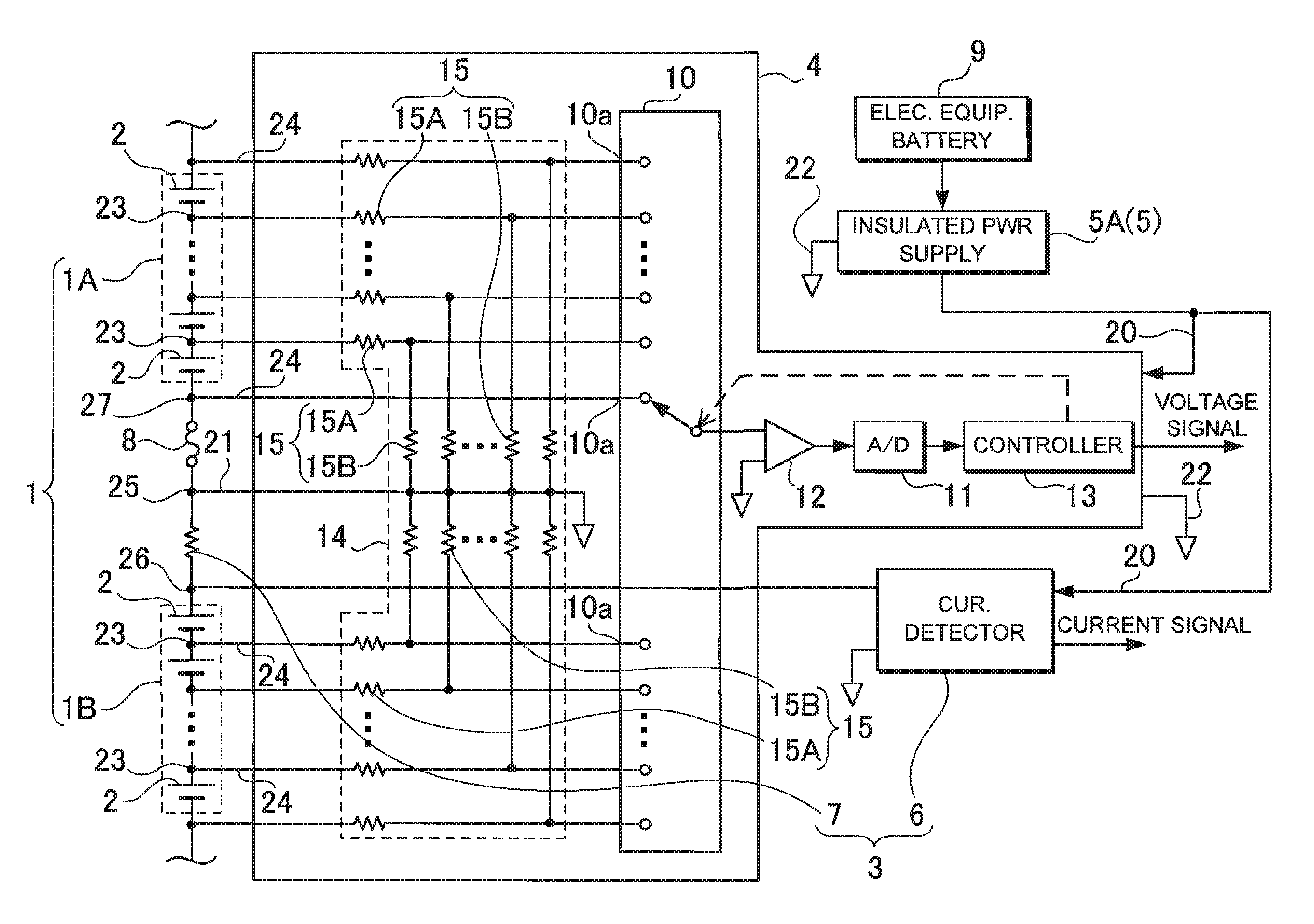
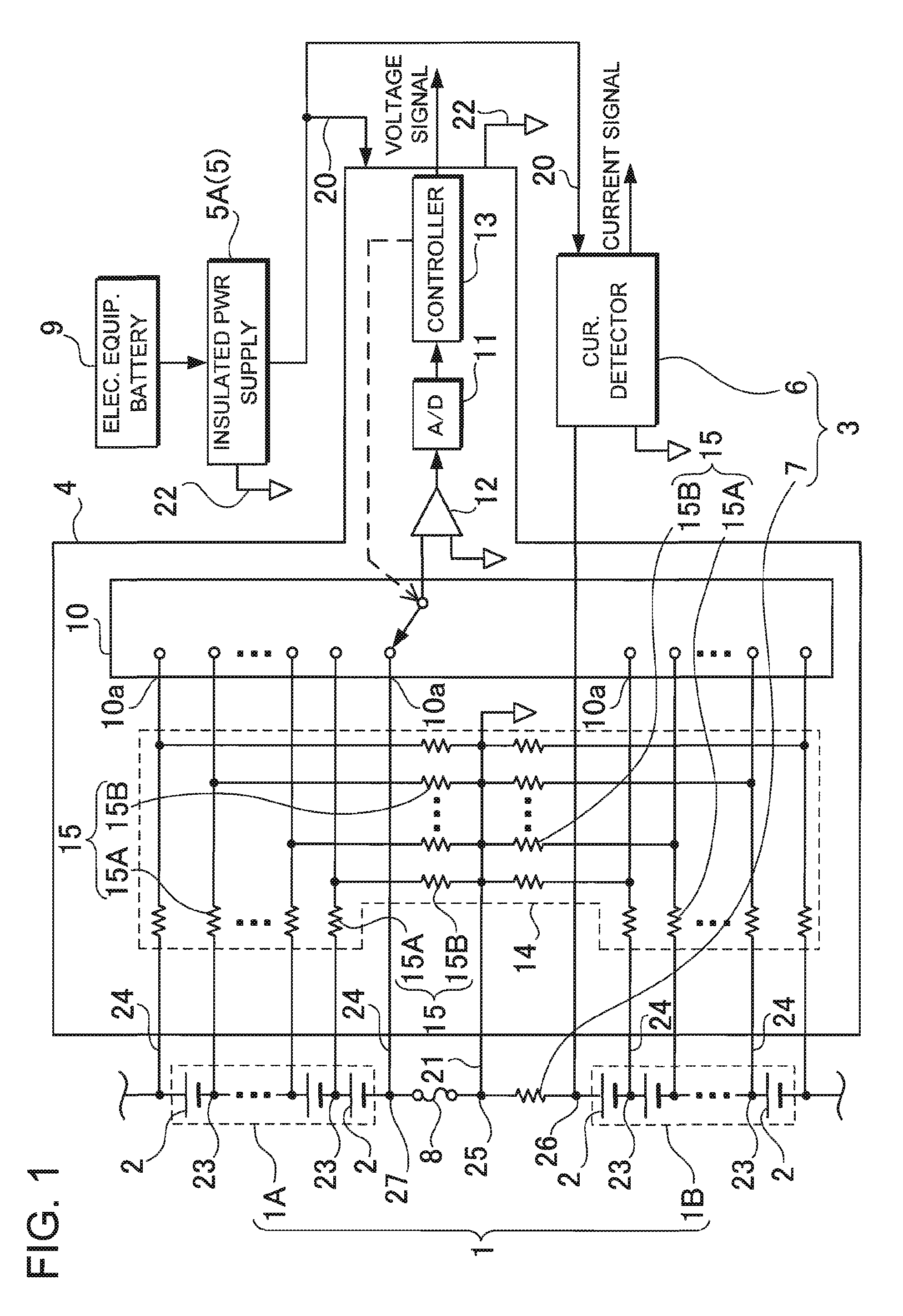
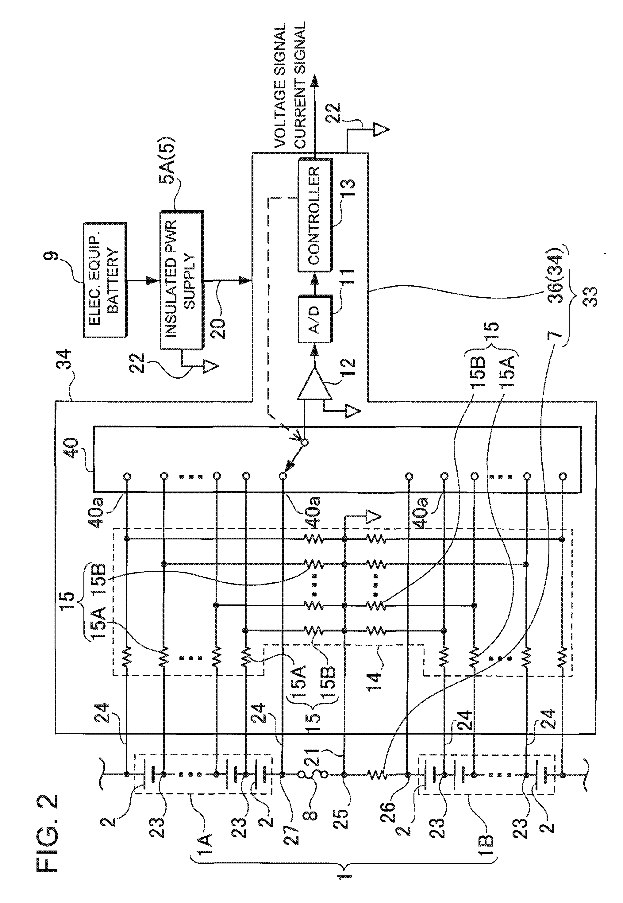
[0027]The vehicle power supply devices shown in FIGS. 1 through 3 include a high-voltage battery portion 1, a current detecting portion 3, 33 or 53, a voltage detecting circuit 4, 34 or 54, and a power supply circuit 5. The high-voltage battery portion 1 includes a plurality of serially-connected rechargeable batteries. The current detecting portion 3, 33 or 53 detects the current of the high-voltage battery portion 1. The voltage detecting circuit 4, 34 or 54 detects the voltage of the high-voltage battery portion 1. The power supply circuit 5 supplies power to power supply lines 20 of the voltage detecting circuit 4, 34 or 54 and the current detecting portion 3, 33 or 53. The current detecting portion 3, 33 or 53 includes a shunt resistor 7, and a current detecting circuit 6, 36 or 56. The shunt resistor 7 is serially connected to the batteries. The current detecting circuit 6, 36 or 56 detects the current based on the voltage between the both ends of the shunt resistor 7. The po...


PUM


Abstract

The vehicle power supply device includes a high-voltage battery portion 1 that includes a plurality of serially-connected rechargeable batteries, a current detecting portion 3 that detects the current of the battery portion 1, a voltage detecting circuit 4 that detects the voltage of the battery portion 1, and a power supply circuit 5 that supplies power to power supply lines 20 of the voltage detecting circuit 4 and the current detecting portion 3. The current detecting portion 3 includes a shunt resistor 7 serially connected to the batteries, and a current detecting circuit 6 for detecting the current based on the voltage between the ends of the shunt resistor 7. The power supply circuit 5 is an insulated-type power supply circuit 5A insulated from a vehicle chassis ground. The power supply circuit 5A supplies power to the power supply lines 20.

Description

BACKGROUND OF THE INVENTION[0001]1. Field of the Invention[0002]The present invention relates to a vehicle power supply device that includes a high-voltage battery portion for supplying power to electric motors to run vehicles, and in particular to a vehicle power supply device that includes a circuit for detecting detects the voltage and the current of the batteries composing a high-voltage battery portion.[0003]2. Description of the Related Art[0004]Vehicle power supply devices that are installed in electric vehicles such as hybrid cars include a high-power high-voltage battery portion. This type of power supply device supplies power to an electric motor of a vehicle from a high-voltage battery portion to run the vehicle by the electric motor. In hybrid cars, vehicles run both by an electric motor driven by a power supply device, and by an internal-combustion engine. The hybrid cars drive an electric generator by the internal-combustion engine to charge a high-voltage battery port...

Claims


Application Information

Patent Timeline
Patent Type & Authority Applications(United States)
IPC IPC(8): H02J7/00B60L3/00B60R16/03B60R16/04G01R31/36H02J7/02
CPCB60L3/0046Y02T10/7055H02J7/0016B60L3/12B60L58/10B60L58/14B60L58/15B60L58/16B60L58/18B60L2240/547Y02T10/70
Inventor YUGOU, MASAKI
Owner SANYO ELECTRIC CO LTD
Learn More