
Electrical Machinery Incorporating Double Helix Coil Designs For Superconducting and Resistive Windings

a technology of resistive windings and electric machinery, applied in the direction of magnetic circuit rotating parts, electric generator control, magnetic circuit shape/form/construction, etc., can solve the problem of significant cost increase in design of reliability improvements

Inactive Publication Date: 2009-12-03
ADVANCED MAGNET LAB
View PDF10 Cites 33 Cited by
  • Summary
  • Abstract
  • Description
  • Claims
  • Application Information

AI Technical Summary

Benefits of technology

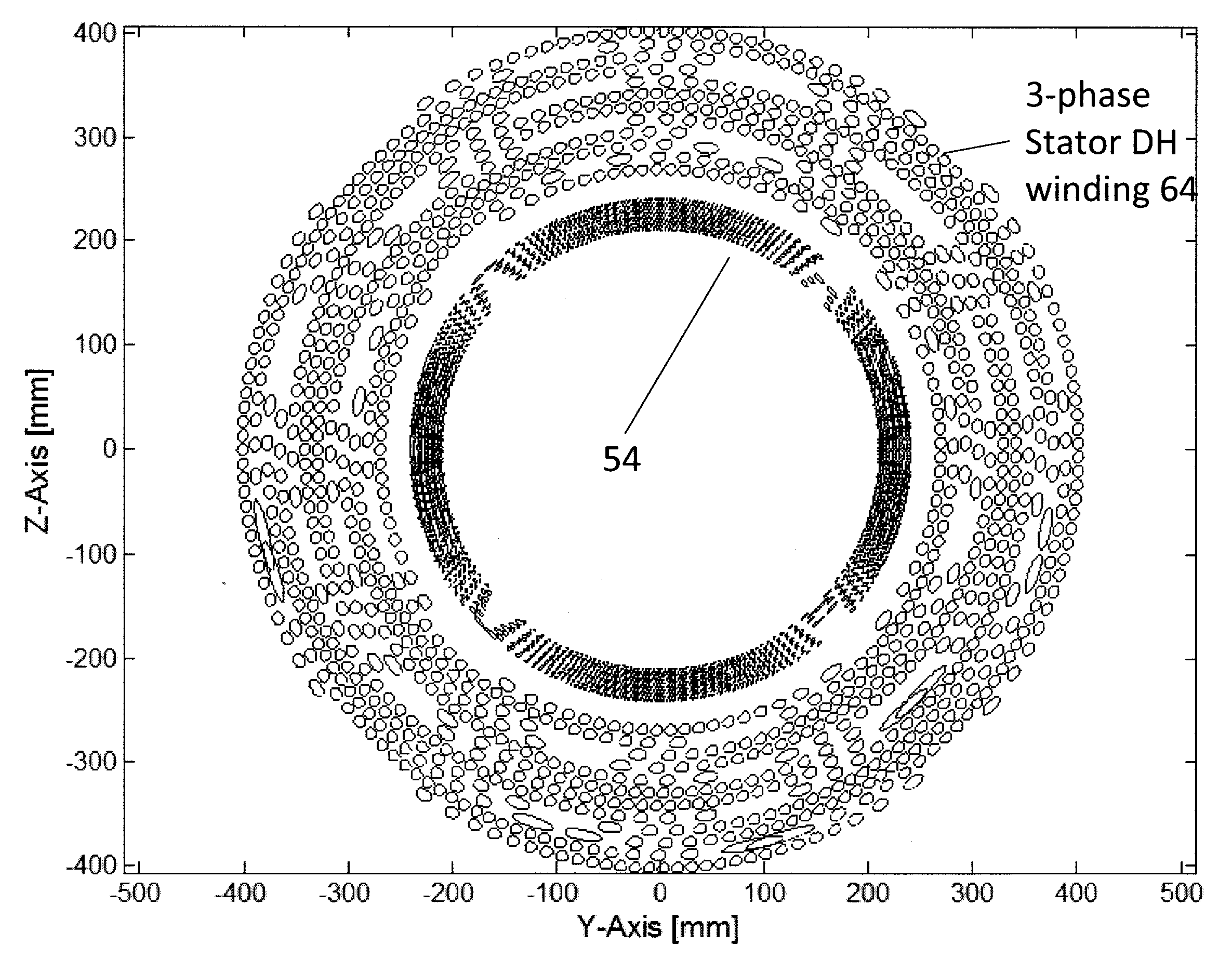
[0017]If the ratio of stator thickness to RC is greater than 25 percent, then the mutual inductance of a first one of the sets of coil rows can be within 10% percent of the mutual inductance of a second one of the sets of coil rows. In one example, during operation, the axial field generated by the first set of coil rows may be less than ten percent of the transverse field generated by the first second set of coil rows. Also, a first member C2n or C′2,n of a pair of coil rows in the second set, may be positioned in the sequence between members C1,n and C′1,n of a pair of coil rows in the first set. Further, a first member C1,n or C′1,n of first pair of coil rows in the first set may be positioned in the sequence between members C3,n and C′3,n of a pair of coil rows in the third set. Within the first set of coil rows, the first member C1,n or C′1,n of the first pair of coil rows in the first set may have a different number of turns, or a different rate of advance per turn in a direction parallel with the axis, than the other member of the first pair of coil rows in the first set.

Problems solved by technology

Designs which improve reliability add significantly to cost.

Method used


Image

  • Electrical Machinery Incorporating Double Helix Coil Designs For Superconducting and Resistive Windings
  • Electrical Machinery Incorporating Double Helix Coil Designs For Superconducting and Resistive Windings
  • Electrical Machinery Incorporating Double Helix Coil Designs For Superconducting and Resistive Windings

Examples


Embodiment Construction

[0029]Before describing in detail the particular methods and apparatuses related to embodiments of the invention, it is noted that the present invention resides primarily in a novel and non-obvious combination of components and process steps. So as not to obscure the disclosure with details that will be readily apparent to those skilled in the art, certain conventional components and steps have been omitted or presented with lesser detail, while the drawings and the specification describe in greater detail other elements and steps pertinent to understanding the invention. Further, the following embodiments do not define limits as to structure or method according to the invention, but only provide examples which include features that are permissive rather than mandatory and illustrative rather than exhaustive.

[0030]The following patents and patent applications, all assigned to the assignee of the present invention, are incorporated herein by reference: U.S. Pat. No. 6,921,042 (hereaf...


PUM


Abstract

An alternating current machine which generates a magnetic field or induces a voltage. In one the machine includes a stator and a rotor positioned about an axis. The stator includes three sets of coils, each set including at least a first pair of coil rows wired in series, with first and second members of the first pair configured to generate axial fields in opposite directions. Coil rows in the first pair of each set of coils are each arranged a different distance from the axis. A first member of the pair of the second set of coil rows is positioned between the first and second members of the pair of the first set of coil rows. The distance between the axis and the first member of the second pair of coil rows is intermediate the distances between the members of the first pair of coil rows and the axis.

Description

RELATED APPLICATION[0001]This application claims priority to provisional patent application U.S. 61 / 130,649 filed 2 Jun. 2008 which is incorporated herein by reference in the entirety.FIELD OF THE INVENTION[0002]This invention relates to electromagnetic systems, including systems which generate magnetic fields, systems which generate electric power, motors, and magnets generally. More particularly, the invention relates to electrical machine systems of the type including conductor assemblies which, when conducting current, generate a magnetic field or which, in the presence of a changing magnetic field, induce voltage.[0003]A wide variety of magnet designs are used for electromechanical applications, including rotating machines such as those used for electric power generation. Applications for electric motors and generators can benefit by use of superconducting magnets whose higher magnetic fields enhance performance and substantially reduce the size and cost of such equipment.[0004...

Claims


Application Information

Patent Timeline
IPC IPC(8): F03D9/00H02K3/28
CPCF03D9/002H02K3/28H02K7/1838Y02E10/725Y02E40/625H02K55/04F03D9/25F03D80/60Y02E10/72Y02E40/60
Inventor MEINKE, RAINERMASSON, PHILIPPEISHMAEL, SASHA
Owner ADVANCED MAGNET LAB
Learn More