
Adjustable Traction System and Method for Footwear

a traction system and adjustable technology, applied in footwear, apparel, applications, etc., can solve the problems of 7.5 mm height, damage to putting greens, and grass roots damage, and achieve different tractional effects and provide traction adjustability.

Inactive Publication Date: 2009-12-03
PRIDE MFG CO LLC
View PDF17 Cites 10 Cited by
  • Summary
  • Abstract
  • Description
  • Claims
  • Application Information

AI Technical Summary

Benefits of technology

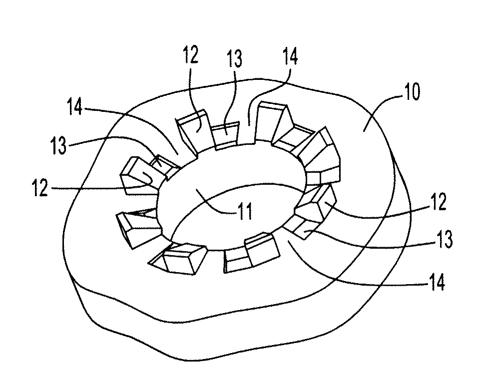
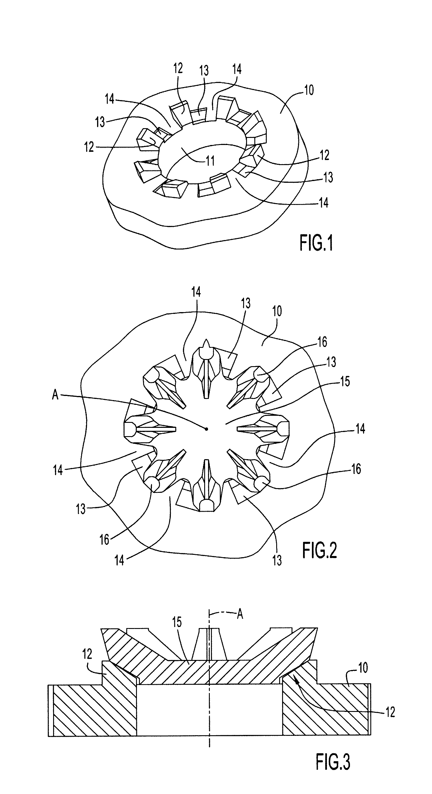
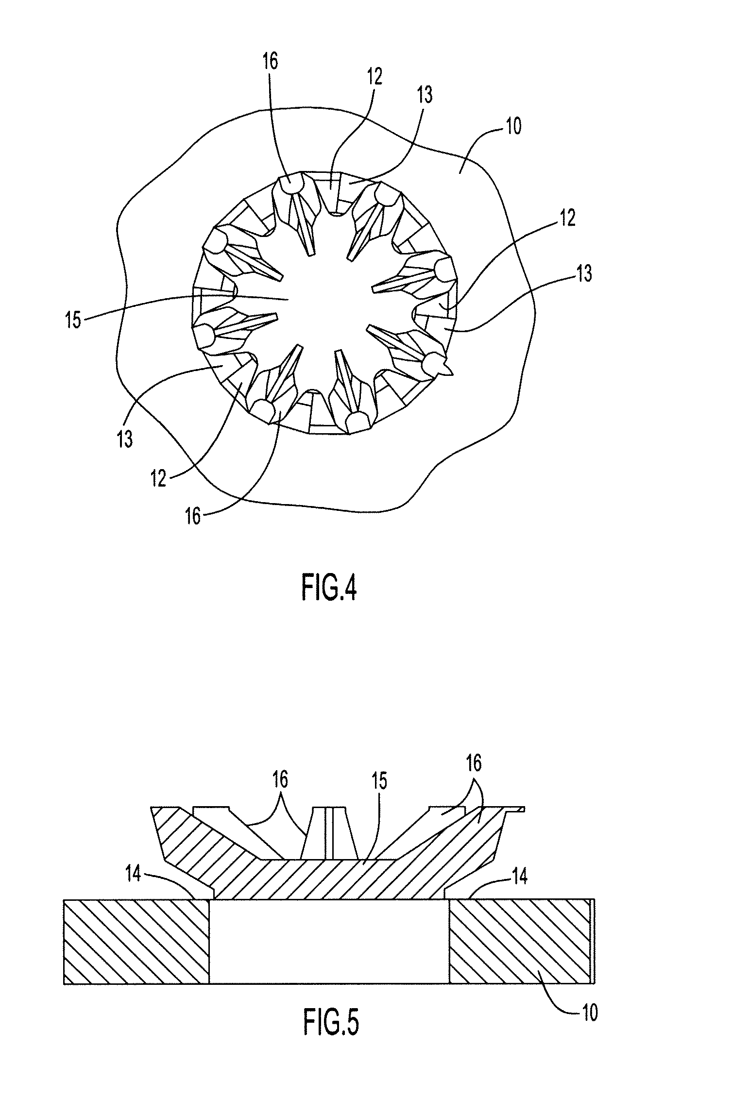
[0013]It is an object of the invention to provide traction adjustability for a cleat in an athletic shoe such that the wearer of the shoe definitively senses and feels different tractional effects. Specifically, it is one object of the present invention to provide in one cleat a choice between at least two, and in some cases more, different cleat “feels” and traction characteristics. More specifically, one embodiment of the invention provides a cleat and outsole combination that allows the user to choose which of the two types of traction “feels” he or she prefers based on how the cleats are selectively installed in the outsole of the golf shoe. Alternatively, the different tractional effects may be provided by an adjustment ring that can be selectively secured to and positioned on the cleat.
[0016]In another aspect of the invention, rather than modifying the bottom surface of the shoe outsole to selectively restrict flexure of dynamic traction elements as a function of the selected rotational starting location, a separate element such as an adjustment ring may be placed on the upper surface of the cleat hub about the cleat connector. In one embodiment the adjustment ring is not rotationally adjustable once mounted and includes spaced depending adjustment segments that are angularly aligned with and positively engage the top surfaces of respective dynamic traction elements so as to prevent the traction element from flexing under the weight of the wearer of the shoe. Alternatively, an adjustment ring may be rotatable and have raised, recessed and / or neutral adjustment segments to interact at different heights with the dynamic traction elements depending on the angular position of the ring on the cleat.

Problems solved by technology

Metal spikes, upon penetration of turf, tend to damage grass roots, a problem that is particularly harmful to golf course greens.
This 7.5 mm height would at times prove to be damaging to putting greens except for the fact that the dynamic traction elements flex under the weight of the golfer, thereby spreading outwardly along the surface of the green without puncturing the turf.
These cleats, although made of plastic material, are rigid and, because of their reduced height, are somewhat less effective in tangling or even biting into grass or thatch as the golfer walks on fairways and in rough.
However, the differences between the tractional effects produced in the three angular positions, both from a tactile perspective and from a tractional function perspective, are subtle at best and are not necessarily sensed or appreciated by the person wearing the shoe.

Method used


Image

  • Adjustable Traction System and Method for Footwear
  • Adjustable Traction System and Method for Footwear
  • Adjustable Traction System and Method for Footwear

Examples


Embodiment Construction

[0042]The following detailed description of FIGS. 1-23 and of the preferred embodiments reveals the methods and apparatus of the present invention. It is to be understood that the relative directional terms “top”, “bottom”, “upward”, downward”, “vertical” and horizontal”, and the like, as used herein, refer to the orientation in a shoe outsole in which the cleat of the invention is installed when the shoe outsole rests on or is forced against a horizontal surface such as the ground, and these terms are not limiting on the orientation of the shoe, the cleat or the scope of the invention. For purposes of understanding, the following directional terms as used herein shall have the following meanings: “angular” means the rotational direction about the central longitudinal axis of the cleat about which the cleat is rotated during installation in a receptacle in a shoe outsole; “radial” refers to the transverse direction perpendicular to the central longitudinal axis; and “axial” refers t...


PUM


Abstract

Tractional characteristics of athletic shoe cleats are adjustable by selectively blocking and unblocking the amount of flexure of dynamic traction elements on the cleat. Blocking is achieved as a function of rotational starting locations during cleat attachment to an outsole receptacle by placing material or recesses in the outsole at different final rotational positions of the tractional elements. Alternatively, adjustability is obtained by attaching and angularly positioning a separate member, such as a ring, on the cleat with segments of the member positioned or not to block traction element flexure.

Description

CROSS REFERENCE TO RELATED APPLICATIONS[0001]This application claims priority under 35 U.S.C. §119(e) from U.S. Provisional Patent Application Ser. No. 61 / 057,311, filed May 30, 2008, and entitled “Adjustable Traction Cleat For Footwear,” the entire contents of which are hereby incorporated by reference.BACKGROUND OF THE INVENTION[0002]1. Technical Field[0003]The present invention pertains generally to methods and apparatus for enhancing traction for footwear and, more particularly, to improvements in footwear and cleats to permit the resulting traction to be selectively adjusted for different conditions and preferences. Although described primarily in connection with golf shoes, it will be understood that the present invention has applicability for any shoe in which a traction cleat is utilized.[0004]2. Discussion of the Prior Art[0005]Historically, traction for golf shoes was provided by pointed or downwardly conically converging metal spikes that penetrate turf. The metal spikes ...

Claims


Application Information

Patent Timeline
Patent Type & Authority Applications(United States)
IPC IPC(8): A43B5/00A43C15/00
CPCA43C15/162A43C15/161
Inventor KRIKORIAN, RAND J.
Owner PRIDE MFG CO LLC
Learn More