
Image Projection Display System

a projection image and display system technology, applied in the field of projection image display system, can solve the problems of reduced image brightness and contrast, large size and/or mass, and complex optical system

Inactive Publication Date: 2009-11-26
OPTYKA
View PDF9 Cites 27 Cited by
  • Summary
  • Abstract
  • Description
  • Claims
  • Application Information

AI Technical Summary

Benefits of technology

[0026]In another embodiment, the controller controls the variable optical property element to change optical geometric and radiometric characteristics including shape and intensity distribution of an area illuminated on the source image formation device without reducing the amount of illumination passing through the system, and thus image brightness.
[0027]In a further embodiment, the controller controls the variable optical property element to cause display of images with different aspect ratios.
[0036]In a further embodiment, the controller operates such that when liquid crystal material index of refraction is higher than that of the lenses the element acts to achieve anamorphic magnification, and a succession of high and low values of refractive index in the liquid crystal material creates a cylindrical lens of uni-axial power having the effect of making light rays in one plane converge while the rays in an orthogonal plane do not.

Problems solved by technology

Such an optical system is complex.
This makes it expensive to design and / or manufacture, large in size and / or mass.
Also, the reflection that occurs at each refractive optical surface can lead to reduced image brightness and contrast.
Such a precise mechanical positioning system is expensive to design and / or manufacture and is large in size and / or mass.
This complicates the design and / or manufacture and / or operation of both parts of optical system, leading to the problems of complexity outlined above.
However there are problems associated with them.
They can be more difficult to manufacture precisely, leading to image aberration.
Their near optimal performance in one state of an optical system with variable states of magnification and focus is not necessarily optimally suited to other states.
They can be difficult to reposition with respect to other elements in the optical system because translation is usually achieved in a screw-like manner with a rotational motion.
Any misalignment of the optical axis of the aspherical element with that of the screw mechanism will lead to increased off-axis image aberration.
If the image has or does not have certain radiometric, geometric, and temporal characteristics then the observer's image perception is adversely affected.

Method used


Image

  • Image Projection Display System
  • Image Projection Display System
  • Image Projection Display System

Examples


Embodiment Construction

[0037]The invention will be more clearly understood from the following description of some embodiments thereof, given by way of example only with reference to the accompanying drawings in which:—

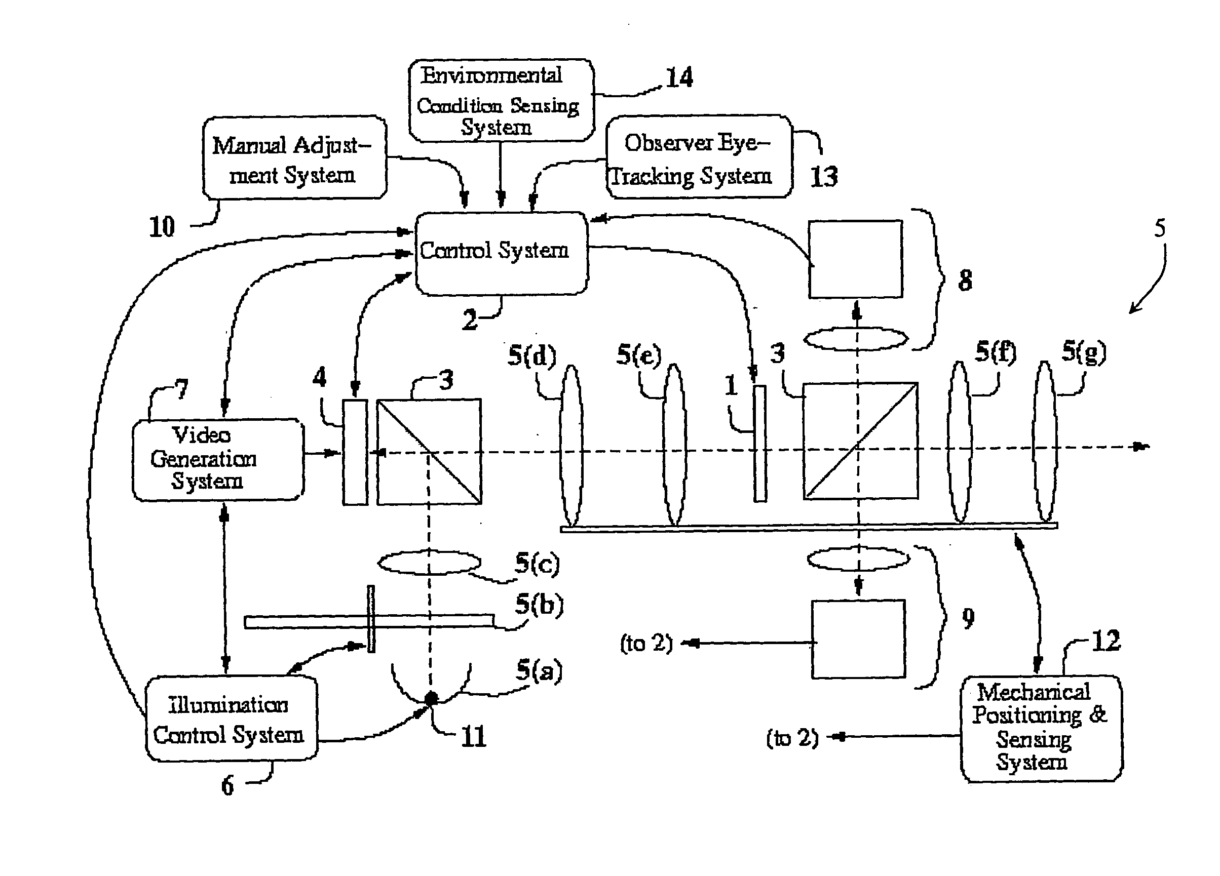
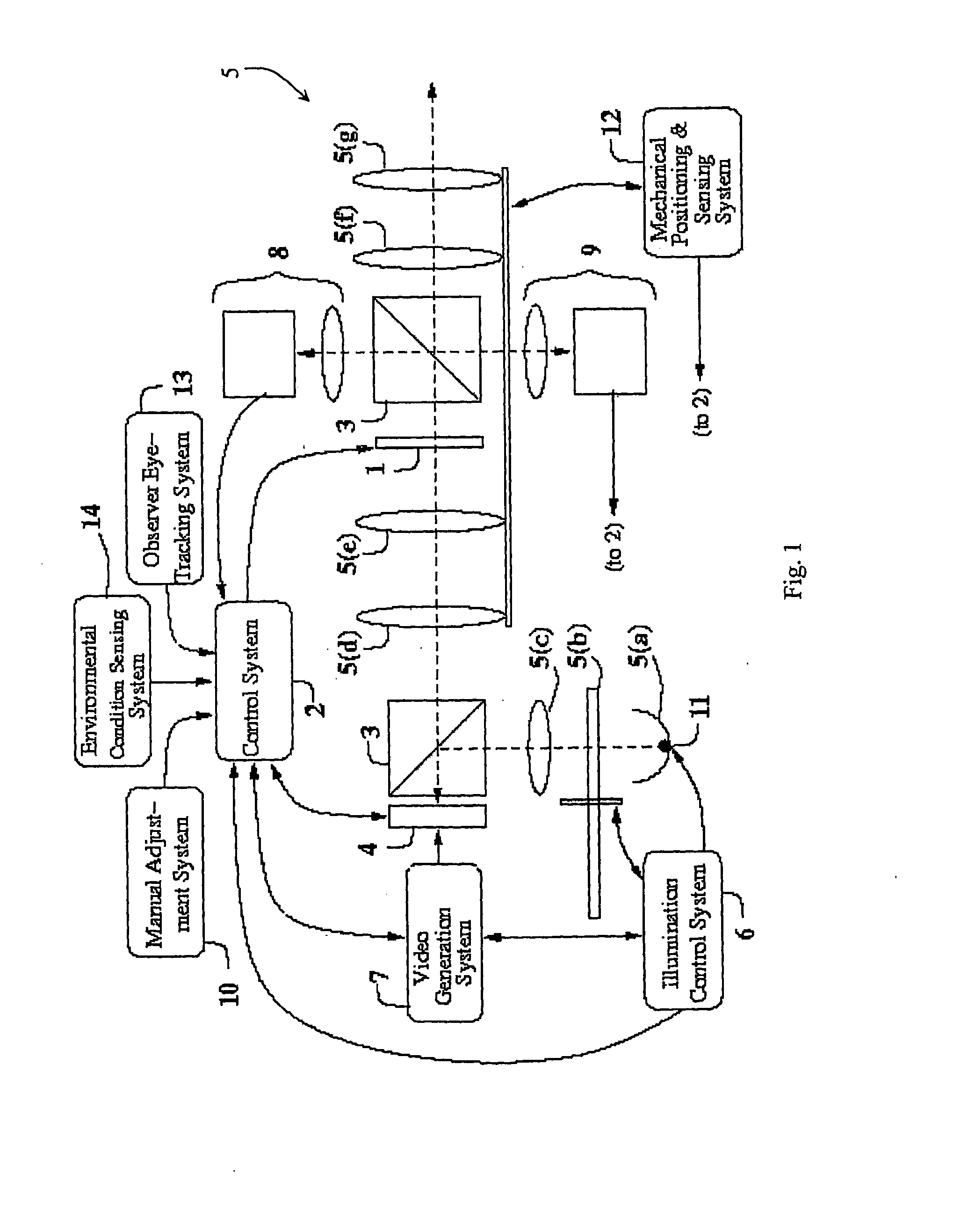
[0038]FIG. 1 is a representation of a projection system of the invention incorporating a variable property optical element;

[0039]FIG. 2 is a ray-tracing schematic of parts of an alternative projection system of the invention;

[0040]FIG. 3 is a diagram showing a variable property optical element, in this embodiment a micro-machined membrane deformable mirror (MMDM);

[0041]FIG. 4 is a diagram of an optical module including two variable optical property elements, in this embodiment MMDMs arranged so as to achieve variable anamorphic magnification;

[0042]FIG. 5 is a representation of a projection system of the invention incorporating variable property optical elements in the illumination path;

[0043]FIG. 6 is another representation of a projection system of the invention incorporating variable prope...


PUM


Abstract

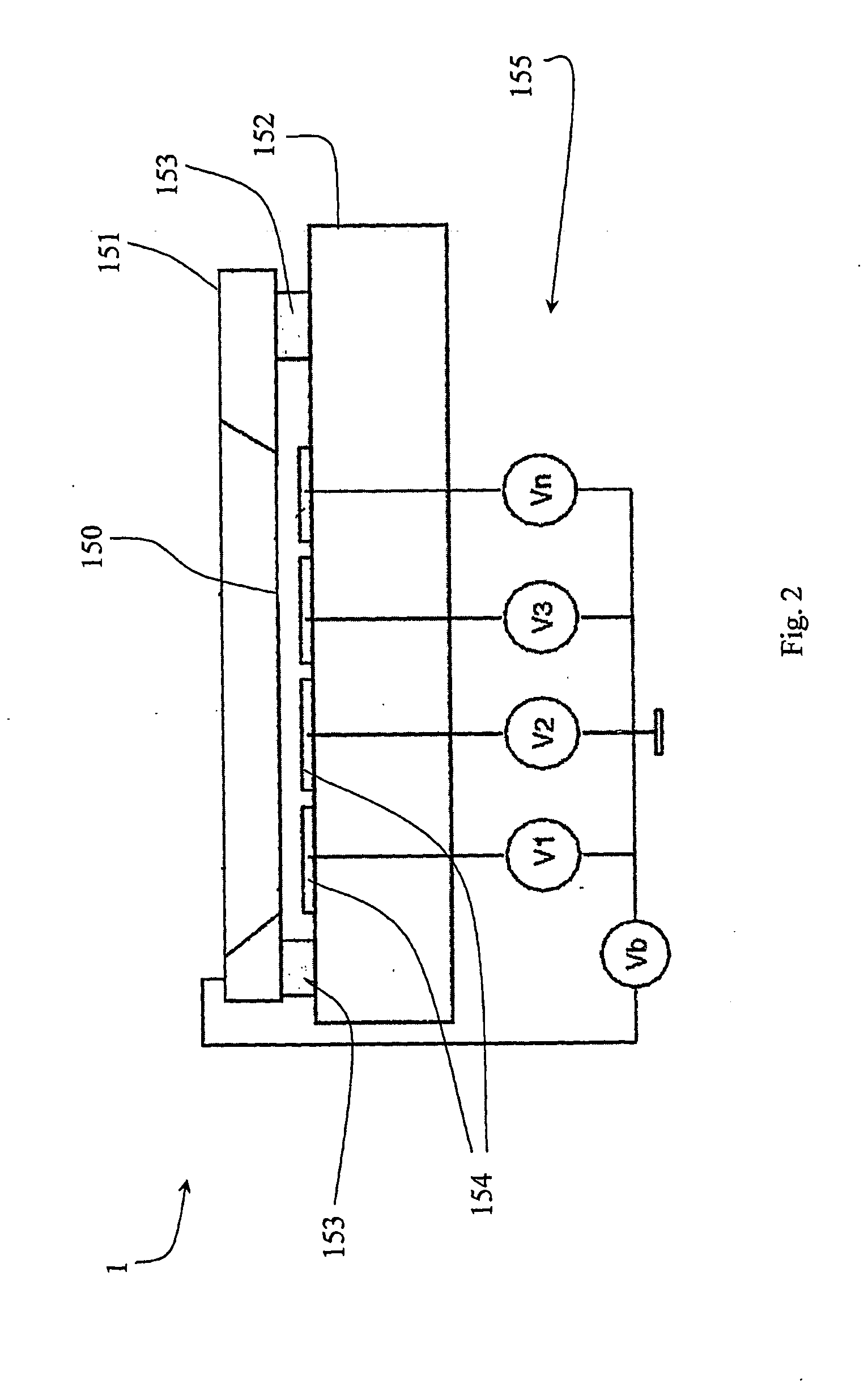
An image projection display system comprises a variable optical property element (1). The element (1) is under direction of a control system (2) and is positioned within an optical system (5), comprising optical elements (5(a, b, c, d, e, f, g)). A source image electronic device (4) receives inputs from a video generation system (7) and is illuminated with light from a photon source (11) filtered by a wavelength-selecting colour wheel (5(b)), under direction of an illumination control system (6). The element 1 comprises a thin Al-coated membrane (150) etched from Sa3N4 (151) mounted via spacers (153) over a substrate (152) having actuator pads (154). Circuits (155) supply various control voltages Electrostatic attraction causes the membrane (150) to deform towards the actuator pads (154) when voltages V1, V2, . . . VN are applied to the actuation channels. The control system (2) receives inputs from the illumination control system (6), the video generation system (J), the source image formation device (4), the mechanical positioning and sensing system (12), and vice-versa.

Description

FIELD OF THE INVENTION[0001]The invention relates to a projection image display system for application such as a video front projector, a rear-projection television, a camera viewfinder, a near-to-eye display, or a photo-lithography system.PRIOR ART DISCUSSION[0002]At present, an approach to achieving good projected image quality in such systems is to use an optical system that achieves low image aberration and low image geometric distortion. The optical system can comprise several groups of optical elements, each element having a precise shape and position, and possibly made of materials with different optical properties relative to the others. Such an optical system is complex. This makes it expensive to design and / or manufacture, large in size and / or mass. Also, the reflection that occurs at each refractive optical surface can lead to reduced image brightness and contrast.[0003]If variation of magnification, focus, and / or image geometric distortion are required, a mechanical posi...

Claims


Application Information

Patent Timeline
IPC IPC(8): G03B21/28H04N9/31G03B21/14
CPCG02B26/06G02B26/0825H04N9/3155G03F7/70308H04N9/3152G03B21/14G03B21/147G03B21/2046
Inventor SHEVLIN, FERGAL
Owner OPTYKA
Learn More