
Viscous material extruding dispenser

a dispenser and viscous material technology, applied in the field of dispensers, can solve the problems of difficult control of quality, control of quality and performance, and difficulty in extruding the appropriate amount of contents, so as to prevent the dispenser from rolling, prevent the occurrence of scratching, and prevent the effect of contents dripping

Active Publication Date: 2009-11-26
YOSHINO KOGYOSHO CO LTD +1
View PDF8 Cites 11 Cited by
  • Summary
  • Abstract
  • Description
  • Claims
  • Application Information

AI Technical Summary

Benefits of technology

[0006]An object of the invention is to propose a novel dispenser which can displace a plunger backward upon interrupting the extrusion of the contents and then certainly induce the accompanying suction effect (back suction) so as to prevent drips or leaks of contents. Another object of the invention is to propose a dispenser which can certainly discharge remaining air entrapped during filling of contents to prevent bubbles from mixing into the contents.

Problems solved by technology

But even after the interruption, the pressing force applied to the plunger remains as residual pressure in a filling space of contents, so that the contents leak out of the tip of the nozzle, which makes it difficult to extrude the appropriate amount of the contents and makes it impossible to utilize the expensive contents without waste.
With such ejecting structure, however, it is difficult to control the quality and to be controlled and perform efficient production since the size of the container is small and such structure requires high accuracy of numerical setting for components so as to cause O-ring torsion.
During setting a plunger in a container, in addition, the O-ring arranged in a groove may be moved to a position farthest from the nozzle side in the groove by the resistance between the O-ring and the container and thus the O-ring torsion, during pressing the plunger, cannot be caused to prevent drips of contents from the tip of the nozzle.

Method used


Image

  • Viscous material extruding dispenser
  • Viscous material extruding dispenser
  • Viscous material extruding dispenser

Examples


Embodiment Construction

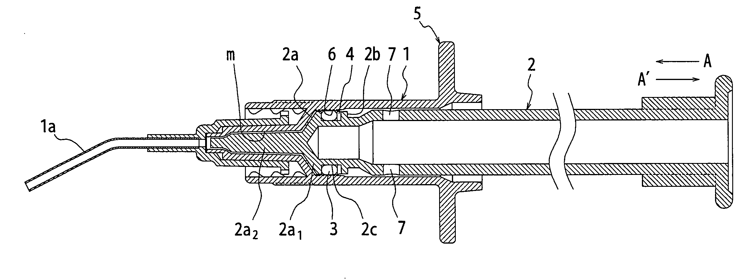
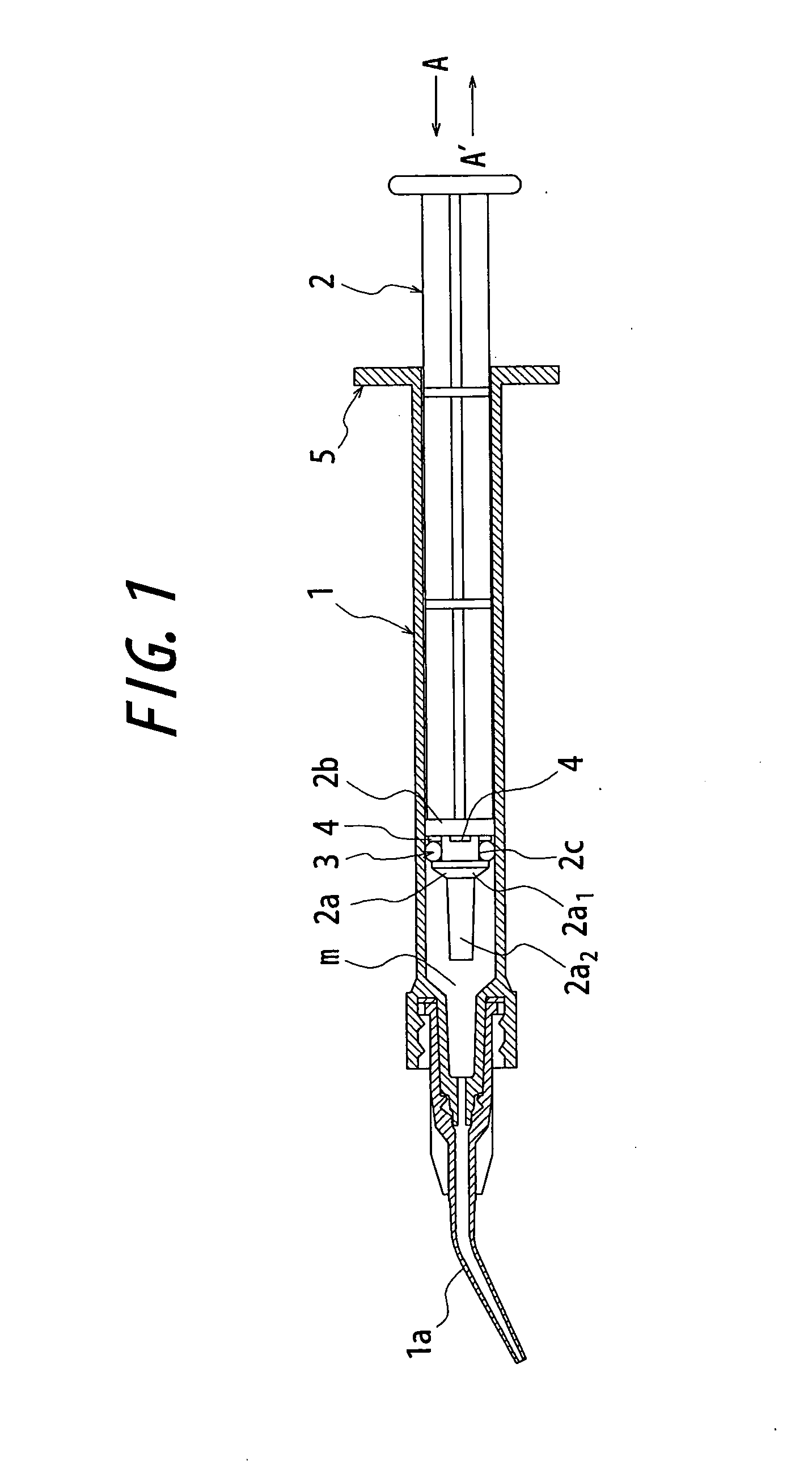
[0039]The invention will be described more concretely with reference to the accompanying drawings. FIG. 1 shows a dispenser for filling a viscous material according to one preferred embodiment of the present invention, and FIG. 2 is an enlarged view of a main portion thereof.

[0040]Reference numeral 1 in the drawings designates a cylindrical syringe body whose front and rear ends are open. The syringe body 1 has a space m for filling contents therein and an extruding nozzle 1a is equipped to the front end of the filling space.

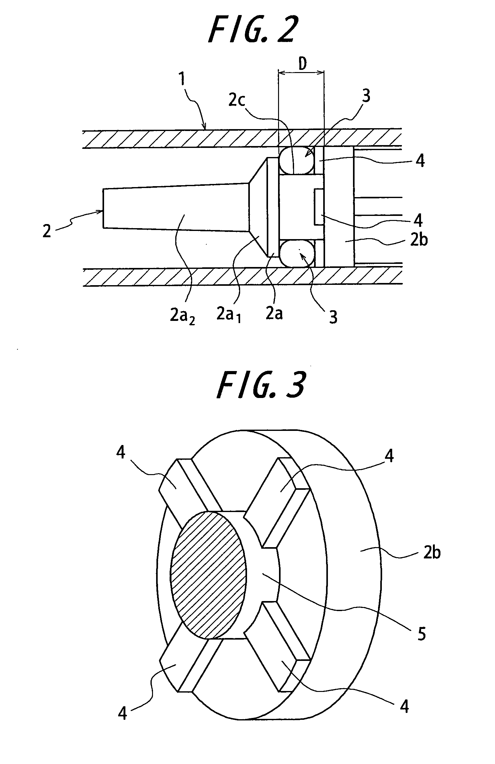
[0041]Reference numeral 2 designates a plunger slid in the syringe body 1 to extrude the contents in the filling space m from the tip of the extruding nozzle 1a. The plunger 2 is provided with a conical disc 2a and a pressing disc 2b at its front section, and an annular groove 2c having the width D is formed between the discs as a defined recess having a flat bottom wall over its entirety (see FIG. 2).

[0042]The conical disc 2a has a shape generally agree with th...


PUM


Abstract

There is provided a dispenser in which an operation load of a plunger is stable and contents of the dispenser do not leak out after pressing operation is interrupted. The invention provides a dispenser comprising a syringe body (1) having a space for filling contents equipped with a extruding nozzle at the front end thereof, a plunger (2) slid, by pressing force applied thereto, in the syringe body (1) to extrude the contents in the filling space (m) from the tip of the extruding nozzle, an O-ring (3) placed in an annular groove (2) formed in the front end section of the plunger and slidable on the inner wall surface of the syringe body (1), wherein the annular groove (2c) is formed as a defined recess having a flat bottom wall over its entirety; a plurality of projections or grooves (4) are formed on the sidewall of the annular groove (2c) with intervals therebetween so that restoring force of the O-rings (3) causes the plunger (2) to slide to the opposite direction of the press-in direction, thus inducing back suction of contents.

Description

TECHNICAL FIELD[0001]The present invention relates to a dispenser suitable for extruding various composites and / or other viscous materials used for dental treatment or the like, and intends to certainly prevent drips of contents from the tip of a nozzle.RELATED ART[0002]A paste material with high viscosity such as composite or an adhesive is often used for dental treatment or the like. A syringe type dispenser is typically used to extrude contents from a small diameter nozzle by pressing a plunger.[0003]With this kind of dispenser, a plunger is operated to extrude contents filled therein usually in multiple stages (i.e. all contents are not extruded by a single operation), and the operation of the plunger is interrupted so as to shut off the extrusion of the contents. But even after the interruption, the pressing force applied to the plunger remains as residual pressure in a filling space of contents, so that the contents leak out of the tip of the nozzle, which makes it difficult t...

Claims


Application Information

Patent Timeline
Patent Type & Authority Applications(United States)
IPC IPC(8): G01F11/00B65D5/72
CPCB05C17/00576A61C5/062A61C5/62B05C5/00B05C17/005
Inventor KUNISHI, HIDETOOHARA, YASUJIROKUWAHARA, KATSUHITOTOMA, TORUSAKAMOTO, SATOSHI
Owner YOSHINO KOGYOSHO CO LTD
Learn More