
Low power, high reliability specific compound functional units

a technology of compound functional units and functional elements, applied in the field of data processing, can solve the problems of time taken for processing circuitry, errors in the operation of these functional elements, and increased likelihood of errors occurring, so as to reduce the total number of compound functional units required, reduce the amount of processing circuitry required, and reduce the number of processing operations.

Inactive Publication Date: 2009-11-12
RGT UNIV OF MICHIGAN +1
View PDF6 Cites 7 Cited by
  • Summary
  • Abstract
  • Description
  • Claims
  • Application Information

AI Technical Summary

Benefits of technology

[0015]The present technique addresses the short path problem by combining multiple functional elements to form compound functional units. Each compound functional unit has at least two evaluation stages, each evaluation stage having at least one functional element. At least one functional element within at least one of the compound functional units includes the Razor circuitry for detecting and recovering from errors. Processing operations are executed by the functional elements in each evaluation stage as intermediate data values pass from stage to stage in successive clock cycles. Short path errors are prevented by controlling the flow of input values into the compound functional units such that the input values for the first of the evaluation stages of the compound functional units are changed at most every second clock cycle. This means that the second evaluation stage will begin processing the output value from the first evaluation stage before the first evaluation stage has been provided with its next input value. Since the interval between the first and second sampling times is less than one clock cycle, the second sampling time will always occur before the second set of input values is provided to the first stage of the compound functional units, thus avoiding the short path problem. Using compound functional units in this way means that the processing throughput of the apparatus is higher than if each individual functional element was clocked every other cycle.
[0039]It is possible that the same group of processing operations may be identified in more than one instance in the data flow graph. In this case, the generating step generates machine-readable data for a single compound functional unit that can perform each instance of the same group of processing operations. By reusing a compound functional unit in this way, less hardware is needed, thus saving on circuit area and power consumption.

Problems solved by technology

However, if the voltage or frequency is scaled too aggressively, then the likelihood of errors occurring may increase.
A critical issue for dynamic voltage and frequency scaling enabled computer systems is determining the safe operating voltage or frequency at which maximum execution efficiency is achieved, whilst still guaranteeing correct operation of all components.
If other functional elements in the system have used the output value at the first sampling time for further processing operations, then errors may arise in the operation of these functional elements due to using the incorrect value.
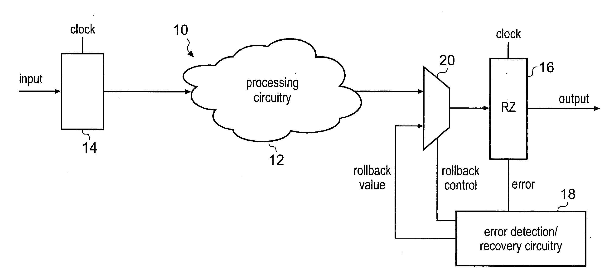
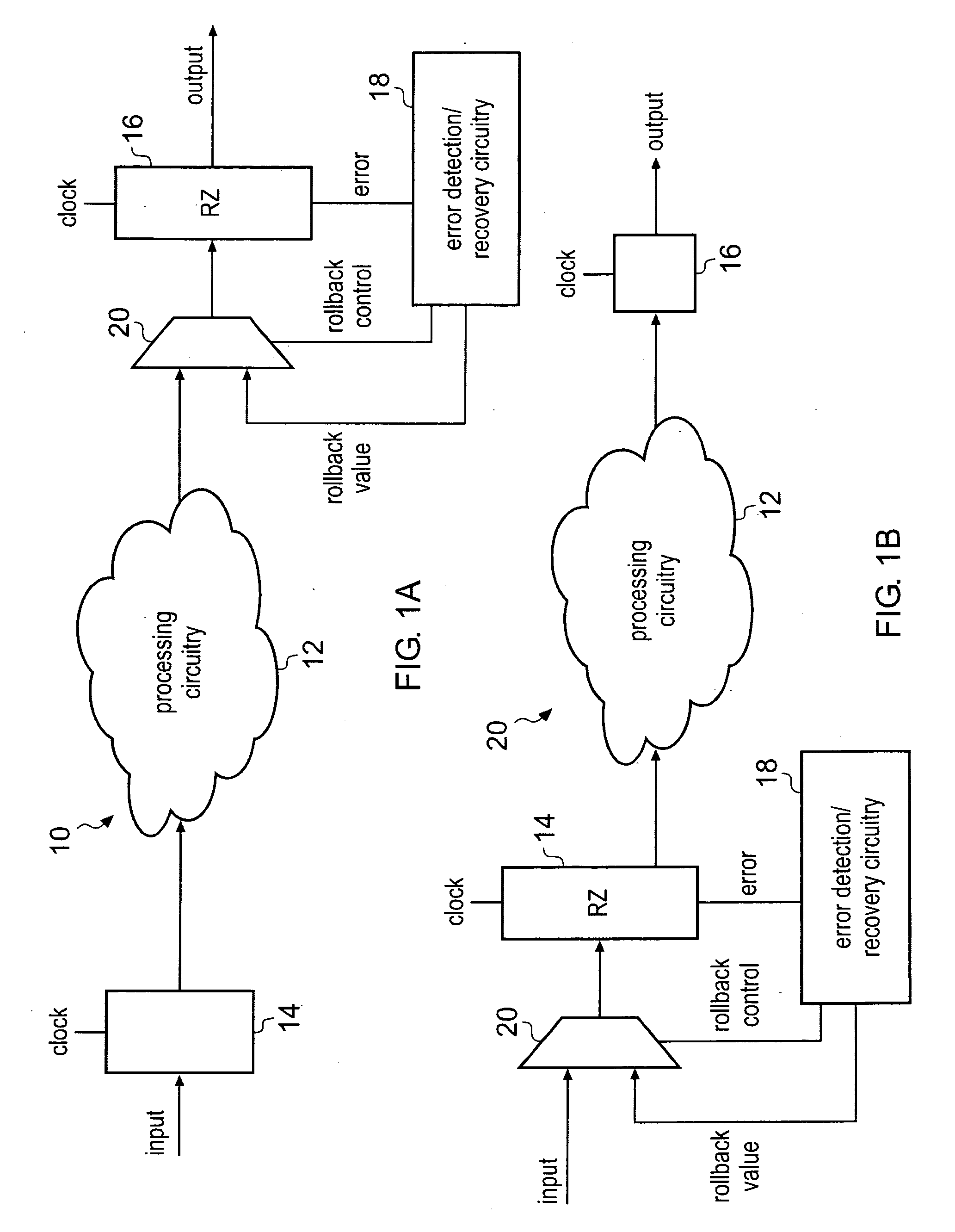
The use of Razor latches can cause a problem if the time taken for the processing circuitry 12 to produce its output value is particularly short.
This will result in a false positive detection of an error.
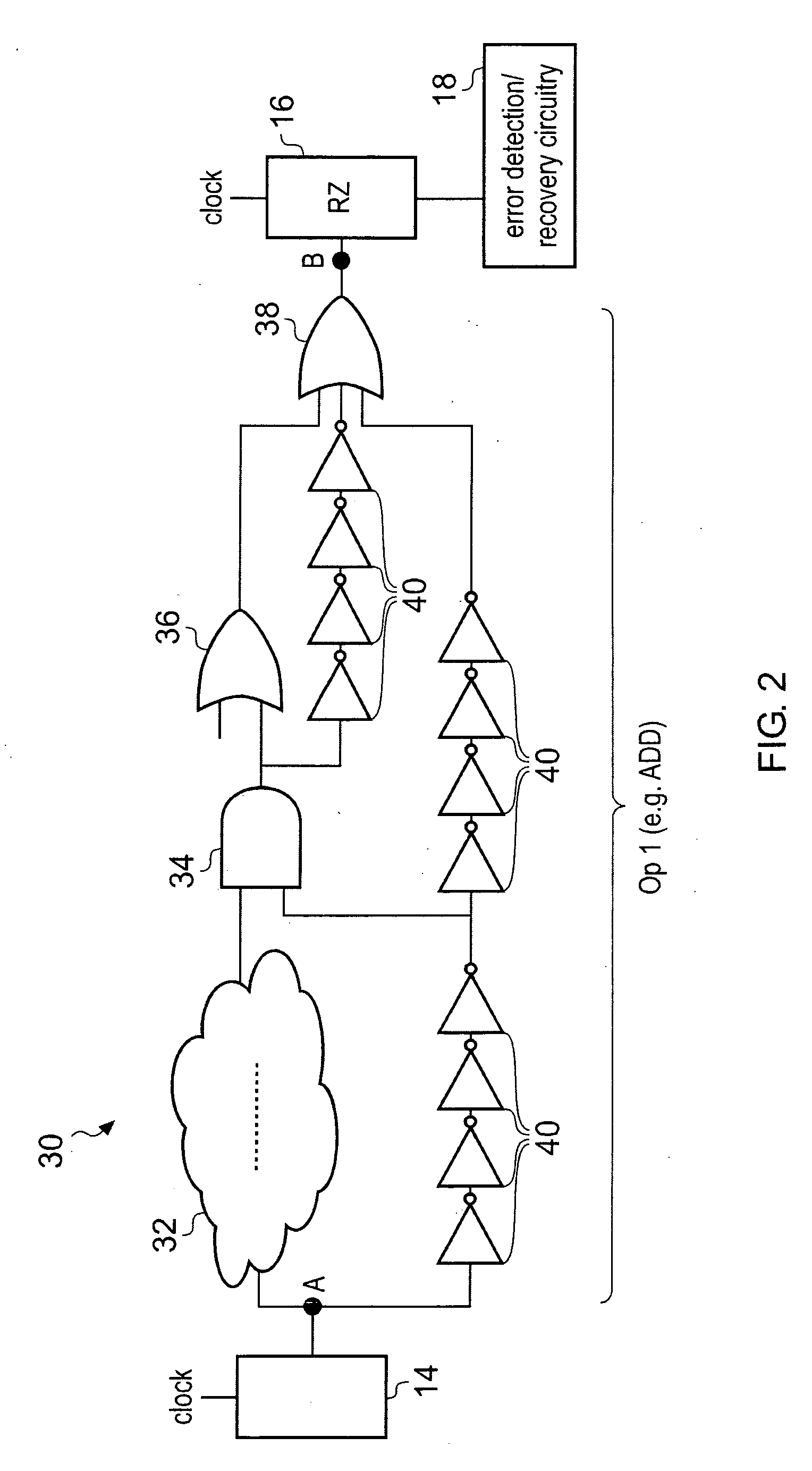
For this reason, this type of false detection of an error is known as a short path error.
Short path errors can trigger an error recovery operation unnecessarily, which will be costly in terms of time and power required for the processing operations.
Also, short path errors could cause further errors at later stages of processing if the value at the second sampling time (i.e. the value produced by the processing circuitry 12 one cycle later than the actual value) is used by subsequent functional elements.
However, adding extra buffers is costly in terms of area and energy consumption, thereby impacting on any gains achieved through dynamic voltage and frequency scaling.

Method used


Image

  • Low power, high reliability specific compound functional units
  • Low power, high reliability specific compound functional units
  • Low power, high reliability specific compound functional units

Examples


Embodiment Construction

[0052]FIG. 3 shows a compound functional unit 50 according to the present technique. In this example the compound functional unit 50 has two evaluation stages, although it will be appreciated that there could be more evaluation stages. The first evaluation stage includes circuitry 52 and gates 54, 56, 58 for performing an ADD operation, for example. The circuitry 52, 54, 56 and 58 collectively make up a functional element. The first evaluation stage has input latches 64, 66 and output latches 68, 70. The second evaluation stage has a functional element for performing a SHIFT operation. The functional element in the second evaluation stage includes gates 60, 62. The output latches 68, 70 for the first evaluation stage are reused as input latches for the second evaluation stage. The second evaluation stage has an output latch 72. In the example shown in FIG. 3, latches 68 and 72 have been provided with error detection / recovery circuitry 80 according to the Razor technique. Again, for ...


PUM


Abstract

To prevent short path errors from occurring in systems having error detection and recovery mechanisms, functional elements are combined to form compound functional units comprising at least two evaluation stages, each evaluation stage including at least one functional element. At least one functional element includes error detection / recovery circuitry. The flow of input values to the first evaluation stage in the compound functional unit is controlled so that the input values are changed at most every second clock cycle.

Description

[0001]This application claims priority from the US provisional Application No. 61 / 052,375, the entire contents of which are incorporated herein by reference.BACKGROUND OF THE INVENTION[0002]1. Field of the Invention[0003]The present invention relates to the field of data processing, and particular data processing systems having error detection mechanisms.[0004]2. Description of the Prior Art[0005]Dynamic voltage and frequency scaling can be used to reduce the overall energy consumption of a computer system, particularly for systems with high variation in processing requirements. Dynamic voltage and frequency scaling can either be used to push the operating conditions of a circuit beyond the nominal operating conditions assumed during design time in order to achieve improved clock frequency, or to reduce energy consumption at times when the full capabilities of the hardware are not required. However, if the voltage or frequency is scaled too aggressively, then the likelihood of error...

Claims


Application Information

Patent Timeline
IPC IPC(8): G06F11/07
CPCG06F11/004G06F11/0793G06F9/3869
Inventor BULL, DAVID MICHAELDASIKA, GANESH SURYANARAYAN
Owner RGT UNIV OF MICHIGAN
Learn More