
Method And System For On-Demand Signal Notching In A Receiver

a receiver and signal technology, applied in the field of signal processing, can solve the problems of increasing the difficulty of designing devices that can reliably operate in such noisy frequency bands, increasing the cost of designing devices, and increasing the difficulty of ensuring the accuracy of the signal notching

Active Publication Date: 2009-11-12
AVAGO TECH INT SALES PTE LTD
View PDF15 Cites 25 Cited by
  • Summary
  • Abstract
  • Description
  • Claims
  • Application Information

AI Technical Summary

Benefits of technology

[0013]A system and/or method is provided for on-demand signal notching in a receiver, substantially as shown i

Problems solved by technology

Additionally, transmit and / or receive circuitry within such mobile wireless devices often account for a significant portion of the power consumed within these devices.
Moreover, in some conventional communication systems, transmitters and / or receivers are often power inefficient in comparison to other blocks of the portable communication devices.
Additionally, as the number of wireless devices and wireless communications standards increase, commonly used frequency bands are becoming increasingly congested with wireless traffic.
In this regard, designing devices that can reliably operate in such noisy frequency bands is becoming increasingly difficult and costly.
In this regard, there may be certain drawbacks associated with 60 GHz communications.
However, even when fabricated on the smallest processes, conventional methods and circuit topologies are often unable to realize signal generation circuits which can generate signals sufficiently high in frequency to enable technologies such as 60 GHz communications.

Method used


Image

  • Method And System For On-Demand Signal Notching In A Receiver
  • Method And System For On-Demand Signal Notching In A Receiver
  • Method And System For On-Demand Signal Notching In A Receiver

Examples


Embodiment Construction

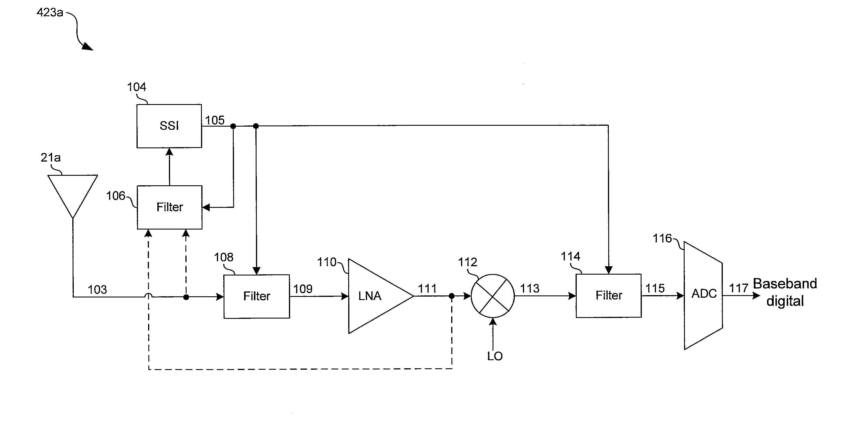
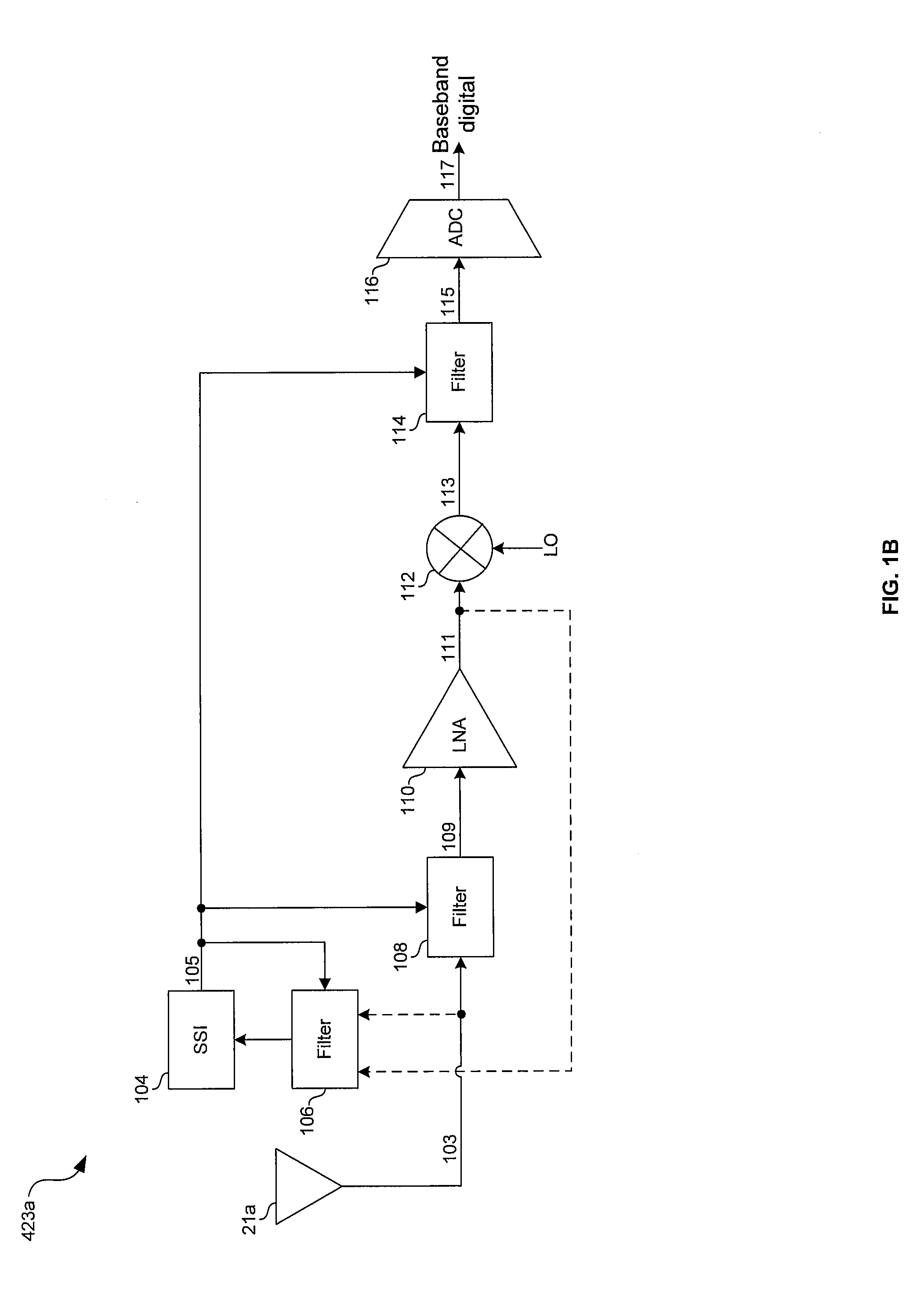
[0022]Certain embodiments of the invention may be found in a method and system for on-demand signal notching in a receiver. In accordance with various embodiments of the invention, signal strength measurements of a received signal may enable detection of unwanted signal component(s), and one or more filters in an on-chip receiver may be configured in response to the measurements. The filter(s) may additionally be configured based on power consumption of the filter(s). Signal measurements and / or the corresponding configuration may be performed dynamically and / or in real-time. The filter(s) may be configured such that a notch in a frequency response of the filter(s) is centered at or near the unwanted component. In this manner, the unwanted component(s) may be filtered out. Unwanted components, which may be in-band and / or out-of-band, may be detected based on, for example, a comparison of the measured strength to one or more thresholds, a signal to noise ratio of the received signal, ...


PUM


Abstract

Aspects of a method and system for on-demand signal notching in a receiver. In this regard, signal strength measurements of a received signal may enable detection of unwanted signal component(s) and one or more filters in an on-chip receiver may be configured in response to the measurements. The filter(s) may additionally be configured based on power consumption of the filter(s). Signal measurements and / or the corresponding configuration may be performed real-time. The filter(s) may be configured such that a notch in a frequency response of the filter(s) is centered at or near the unwanted component. In this manner, the unwanted component(s) may be filtered out. The filter(s) may be configured, for example, by switching one or more filter stages and / or components into and / or out of a signal path and / or by tuning one or more variable circuit elements within the filter(s).

Description

CROSS-REFERENCE TO RELATED APPLICATIONS / INCORPORATION BY REFERENCE[0001]This patent application makes reference to:[0002]U.S. patent application Ser. No. 11 / 954,962 (Attorney Docket No. 19247US01) filed on Dec. 12, 2007;[0003]U.S. patent application Ser. No. 11 / 955,064 (Attorney Docket No. 19254US01) filed on Dec. 12, 2007; and[0004]U.S. patent application Ser. No. ______ (Attorney Docket No. 19249US01) filed on even date herewith.[0005]Each of the above stated applications is hereby incorporated herein by reference in its entirety.FIELD OF THE INVENTION[0006]Certain embodiments of the invention relate to signal processing. More specifically, certain embodiments of the invention relate to a method and system for on-demand signal notching in a receiver.BACKGROUND OF THE INVENTION[0007]Mobile communications have changed the way people communicate and mobile phones have been transformed from a luxury item to an essential part of every day life. The use of mobile phones is today dictate...

Claims


Application Information

Patent Timeline
IPC IPC(8): H04B1/10
CPCH04B1/10H04B1/1036
Inventor ROFOUGARAN, AHMADREZAROFOUGARAN, MARYAM
Owner AVAGO TECH INT SALES PTE LTD
Learn More