Joint transceiver design for MIMO communications

a transceiver and joint technology, applied in the field of multi-input multiple-output (mimo) communication systems, can solve problems such as increased system and hardware complexity

Active Publication Date: 2009-11-12
IND TECH RES INST
View PDF4 Cites 15 Cited by
  • Summary
  • Abstract
  • Description
  • Claims
  • Application Information

AI Technical Summary

Problems solved by technology

While a MIMO system can significantly improve bit error rate (BER) performance while maintaining high data rates, a major concern in the implementation of a MIMO system is the increased system and hardware complexity.

Method used


Image

  • Joint transceiver design for MIMO communications
  • Joint transceiver design for MIMO communications
  • Joint transceiver design for MIMO communications

Examples


Embodiment Construction

[0017]In the following description and claims, the terms “coupled” and “connected,” along with their derivatives, may be used. It is to be understood that these terms are not necessarily intended as synonyms for each other. Rather, in particular embodiments, “connected” and / or “coupled” may be used to indicate that two or more elements are in direct physical or electronic contact with each other. However, “coupled” may also mean that two or more elements are not in direct contact with each other, but yet still cooperate, communicate, and / or interact with each other.

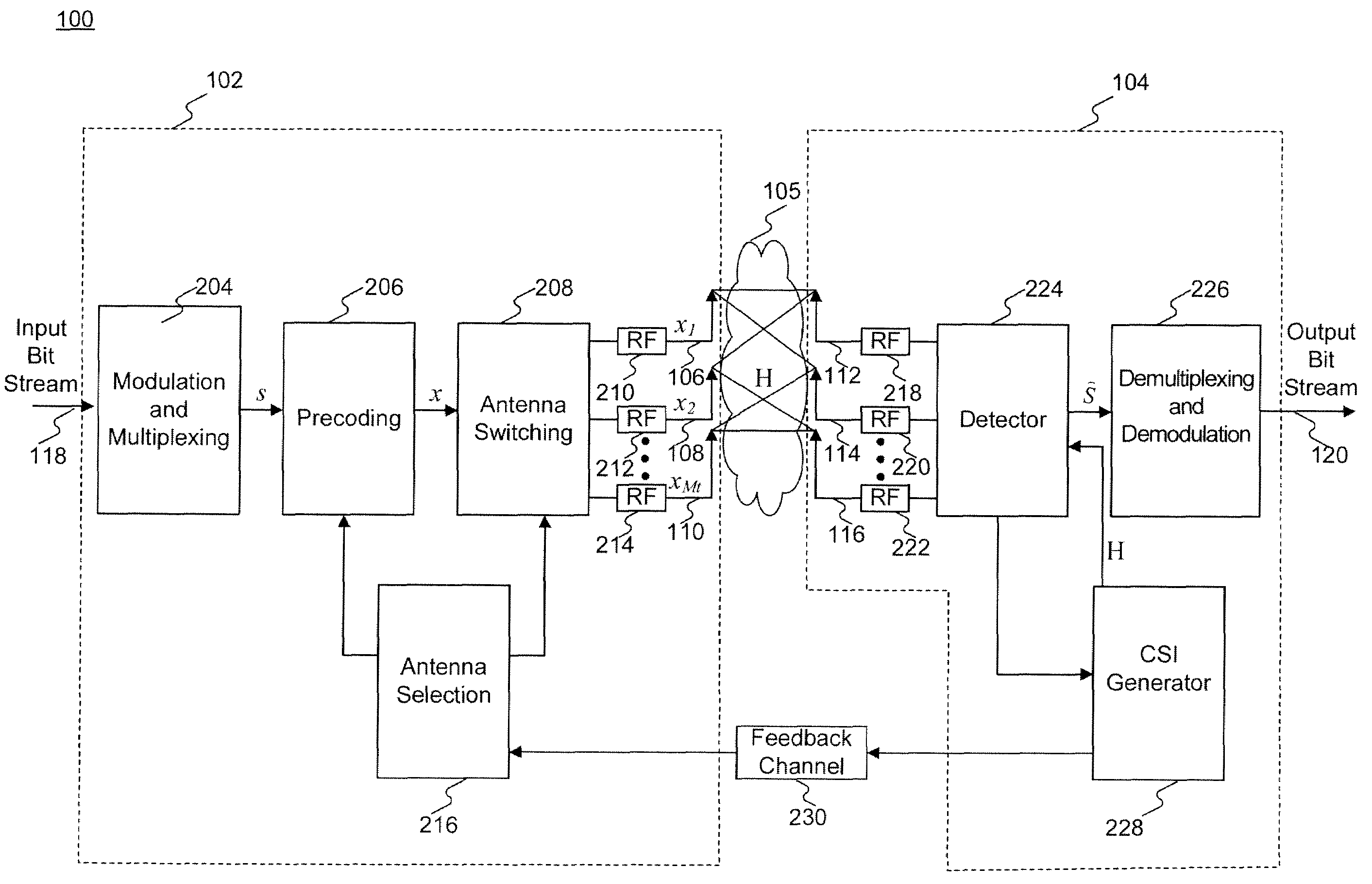
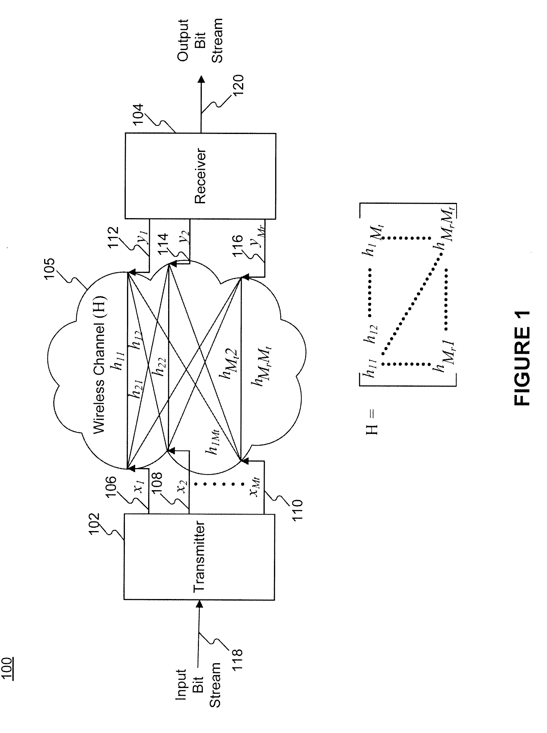
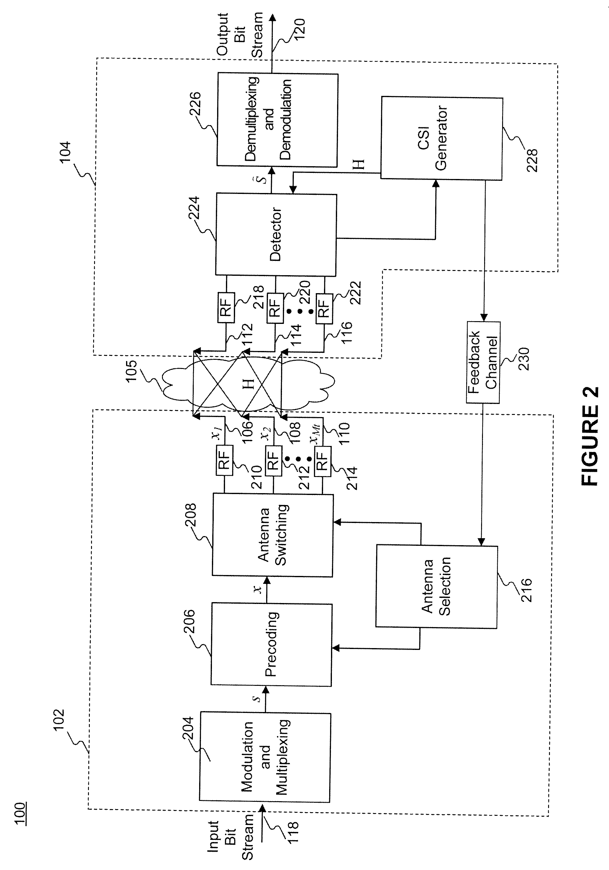
[0018]FIG. 1 illustrates an exemplary MIMO transceiver system 100 in accordance with an embodiment of the present invention. System 100 includes a transmitter 102 and a receiver 104. Transmitter 102 may be part of a base station and receiver 104 may be part of an access point. Conversely, transmitter 102 may be part of an access terminal and receiver 104 may be part of a base station. A base station may be a fixed or mobi...


PUM


Abstract

A method and apparatus for transmitting data in a MIMO communication system, the method including encoding at least one data symbol by implementing a first precoding scheme, the first preceding scheme including a precoder derived from a first channel state information (CSI). The method further includes selecting at least one antenna that maximizes the first CSI, the at least one antenna being selected by implementing a first selection scheme, and transmitting the at least one data symbol via the at least one antenna.

Description

RELATED APPLICATIONS[0001]This application claims the benefit of U.S. Provisional Application No. 61 / 050,972, filed on May 6, 2008, the contents of which are herein incorporated by reference in its entirety.TECHNICAL FIELD[0002]This invention relates to a multiple-input multiple-output (MIMO) communication system and, more specifically, to antenna selection in a MIMO transceiver.DISCUSSION OF RELATED ART[0003]Since the inception of modern wireless communication theory, most communication systems have taken a single-input single-output (SISO) approach, where a single antenna is used at both the transmitter and receiver. However, with increasing demand for faster and more reliable communication systems, multiple-input multiple-output (MIMO) systems are an alternative approach. MIMO communication systems have recently received increased attention due to their potential for providing significantly higher data rates in frequency selective and fading wireless channels.[0004]In a MIMO syst...

Claims


Application Information

Patent Timeline
Patent Type & Authority Applications(United States)
IPC IPC(8): H04B7/02H04L27/00
CPCH04B7/0417H04B7/0691H04B7/061
Inventor MA, HSI-PINHUANG, CHIEN-JENHSU, JEN-YUANTING, PANG-AN
Owner IND TECH RES INST
Why Eureka
Try Eureka