
Communication device and handover method

a communication device and handover technology, applied in the field of communication devices and handover methods, can solve problems such as inability to carry out network operation, provoke network malfunction, and inappropriate ip data packets

Inactive Publication Date: 2009-11-12
PANASONIC CORP
View PDF4 Cites 40 Cited by
  • Summary
  • Abstract
  • Description
  • Claims
  • Application Information

AI Technical Summary

Benefits of technology

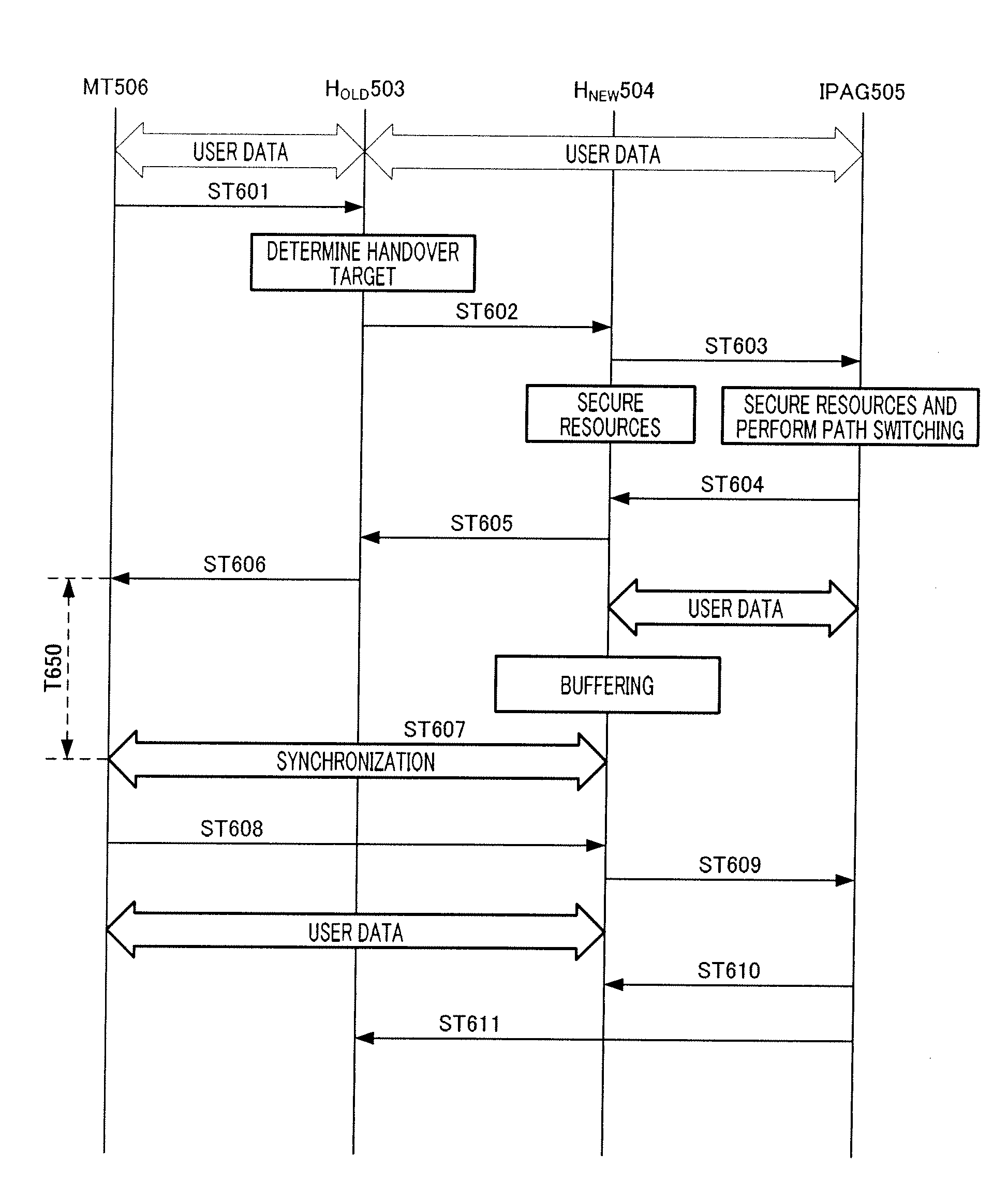
[0015]The present invention performs handover according to traffic types, and can thereby prevent loss of packet data in non-real-time type communication and perform handover at high speed without producing any delay in real-time type communication.

Problems solved by technology

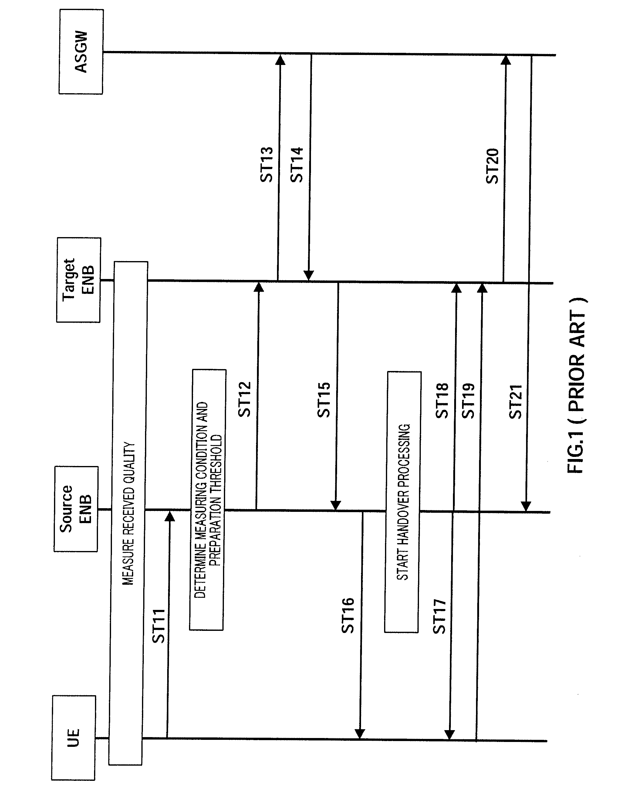
On the other hand, when the deletion fails, one or more hosts react as a proxy for the mobile terminal, which makes routing and assignment of IP data packets inappropriate and provokes unacceptable malfunction of the network.

Method used


Image

  • Communication device and handover method
  • Communication device and handover method
  • Communication device and handover method

Examples


embodiment 1

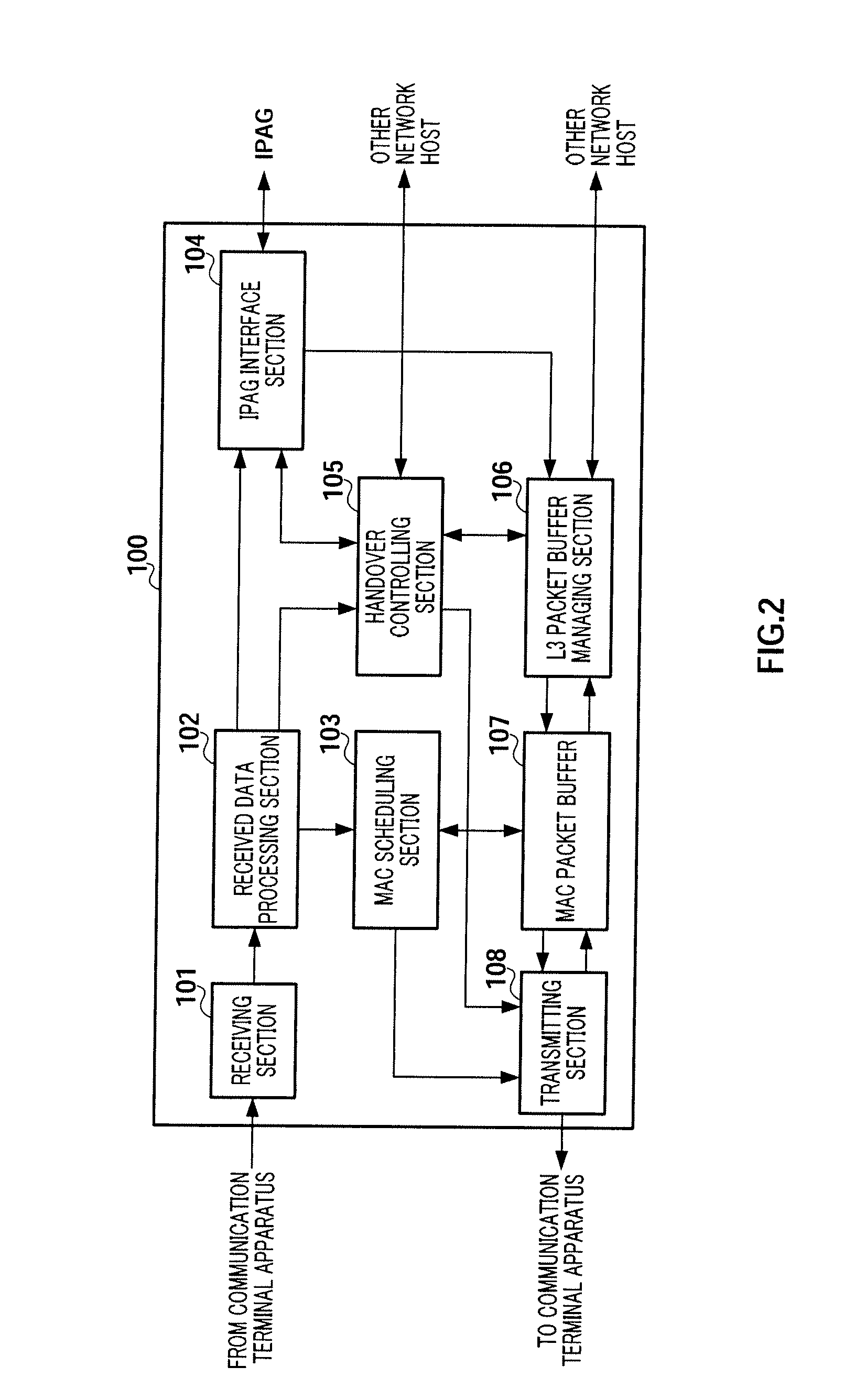
[0027]FIG. 2 is a block diagram showing the configuration of network host 100 which is a communication apparatus according to Embodiment 1 of the present invention.

[0028]Receiving section 101 receives a signal transmitted from a communication terminal apparatus using a radio channel, down-converts the received signal from radio frequency to baseband frequency and outputs the received signal to received data processing section 102.

[0029]Received data processing section 102 demodulates the received signal inputted from receiving section 101 and decomposes the received signal into a data part and a control data part. Received data processing section 102 then outputs the decomposed data part to IP Access Gateway (hereinafter “IPAG”) interface section 104 and also outputs the decomposed control data part to MAC scheduling section 103 and handover controlling section 105.

[0030]MAC scheduling section 103 performs scheduling based on received quality information, which is information of rec...

embodiment 2

[0085]FIG. 8 is a block diagram showing the configuration of handover controlling section 105 according to Embodiment 2 of the present invention. The configuration of the network host in this Embodiment 2 is the same as the configuration in FIG. 2, and therefore explanations thereof will be omitted.

[0086]Buffer managing section 801 outputs a control signal for performing control to L3 packet buffer managing section 106. Furthermore, upon receiving a message showing that preparations for handover have been completed from the handover target network host as input, buffer managing section 801 outputs information of the amount of data stored in L3 packet buffer managing section 106 inputted from L3 packet buffer managing section 106 to transmission end time estimating section 802.

[0087]Transmission end time estimating section 802 calculates a transmission rate at which data can be transmitted with received quality in the received quality information inputted from received data processin...


PUM


Abstract

A communication device can perform handover in accordance with a traffic type. In a non-real time communication, it is possible to prevent loss of packet data. In a real time communication, a handover can be rapidly performed without causing a delay. In this device, a handover control unit (105) judges whether data type information is data in a real time communication. If the data is in a real time communication, the handover control unit (105) outputs a switching request message for switching the path switch to the local station to an IPAG interface unit (104). An L3 packet buffer management unit (106) temporarily accumulates the data transmitted from the IPAG or data transferred from other network host.

Description

TECHNICAL FIELD[0001]The present invention relates to a communication apparatus and a handover method. More particularly, the present invention relates to a communication apparatus and a handover method for performing handover according to traffic types.BACKGROUND ART[0002]Network layer protocols supporting the Internet (hereinafter “IP”) are used to manage and control data that flows in the form of IP data from a source node to a destination node by accessing network or subnetwork making up the Internet. In order to ensure that IP data packets can be delivered, each node is assigned an IP address and the assigned IP address defines a location on fixed network for the corresponding node. IPs are generally designed to support routing of IP packets among fixed network nodes.[0003]However, with the rapid development of radio nodes, there is a growing demand for providing IP support for mobile terminals in the same way as for fixed nodes. Here, fixed nodes generally do not move. Further...

Claims


Application Information

Patent Timeline
IPC IPC(8): H04W36/16H04W28/14H04W36/02H04W36/08H04W36/24H04W36/26H04W36/30H04W36/38
CPCH04W36/0033H04W36/24H04W36/02H04W36/249
Inventor KANAZAWA, TAKESHIISHIDA, HIROSHIKOIDE, YASUO
Owner PANASONIC CORP
Learn More