Hammer drill

a hammer drill and hammer head technology, applied in the direction of portable percussive tools, boring/drilling equipment, drilling machines and methods, etc., can solve the problems of labor-intensive and time-consuming, and the fitter needs extra care, so as to reduce the mechanical load reduce the wear of the retaining ring

Inactive Publication Date: 2009-11-12
AEG ELECTRIC TOOLS
View PDF15 Cites 13 Cited by
  • Summary
  • Abstract
  • Description
  • Claims
  • Application Information

AI Technical Summary

Benefits of technology

[0005]The example hammer drill includes two discs, a retaining disc and non-return disc, to secure the retaining ring in the tool spindle. In this case, the side of the retaining ring facing the beat piece is braced axially against an annular step in the tool spindle via the non-return disc, while the side of the retaining ring facing the striker is braced axially against a locking ring via the retaining disc, the locking ring being set in an annular groove created in the tool spindle. By selecting appropriate materials for the discs, the mechanical load on the retaining ring may be reduced, which in turn significantly reduces wear on the retaining ring. At the same time, the retaining ring may be created from materials that are more suitable for grasping and retaining the striker.
[0006]In one example hammer drill, the retaining ring, the retaining disc and the non-return disc may now each be arranged mirror-symmetrically relative to a centre plane extending perpendicularly to the spindle axis. This configuration precludes the risk of installing the individual elements the wrong way round in the tool spindle. If asymmetrical elements are assembled the wrong way round, the element in question may fail after a very short operating period, and this is therefore undesirable. Installing asymmetrical elements requires extra care on the part of the fitter, which is both labor-intensive and time-consuming. If assembly is automated, additional effort must be expended to prevent any possibility of the elements being installed the wrong way. With the suggested mirror-symmetrical configuration of the individual elements, this additional effort may be avoided. Assembly is correspondingly simpler, and as a result the hammer drill may be manufactured to higher quality specifications and still less expensively.
[0007]Another example hammer drill includes a retaining disc and the non-return disc designed as identical parts. With this construction method, it is not possible to mistake the retaining disc for the non-returning disc or vice versa, and this also serves to simplify assembly, which again results in improved quality while lowering manufacturing costs.
[0008]Of course, it is possible to implement the two solutions together. The advantages associated with such a combination in terms of simpler assembly and enhanced quality are evident.
[0009]A brake ring arranged coaxially with the spindle axis may also be provided, such that a protruding end section of the beat piece advances into this brake ring. This brake ring may now also be configured so as to be mirror-symmetrical about a centre plane extending perpendicularly to the spindle axis. This also serves to simplify assembly.

Problems solved by technology

If asymmetrical elements are assembled the wrong way round, the element in question may fail after a very short operating period, and this is therefore undesirable.
Installing asymmetrical elements requires extra care on the part of the fitter, which is both labor-intensive and time-consuming.

Method used


Image

  • Hammer drill
  • Hammer drill
  • Hammer drill

Examples


Embodiment Construction

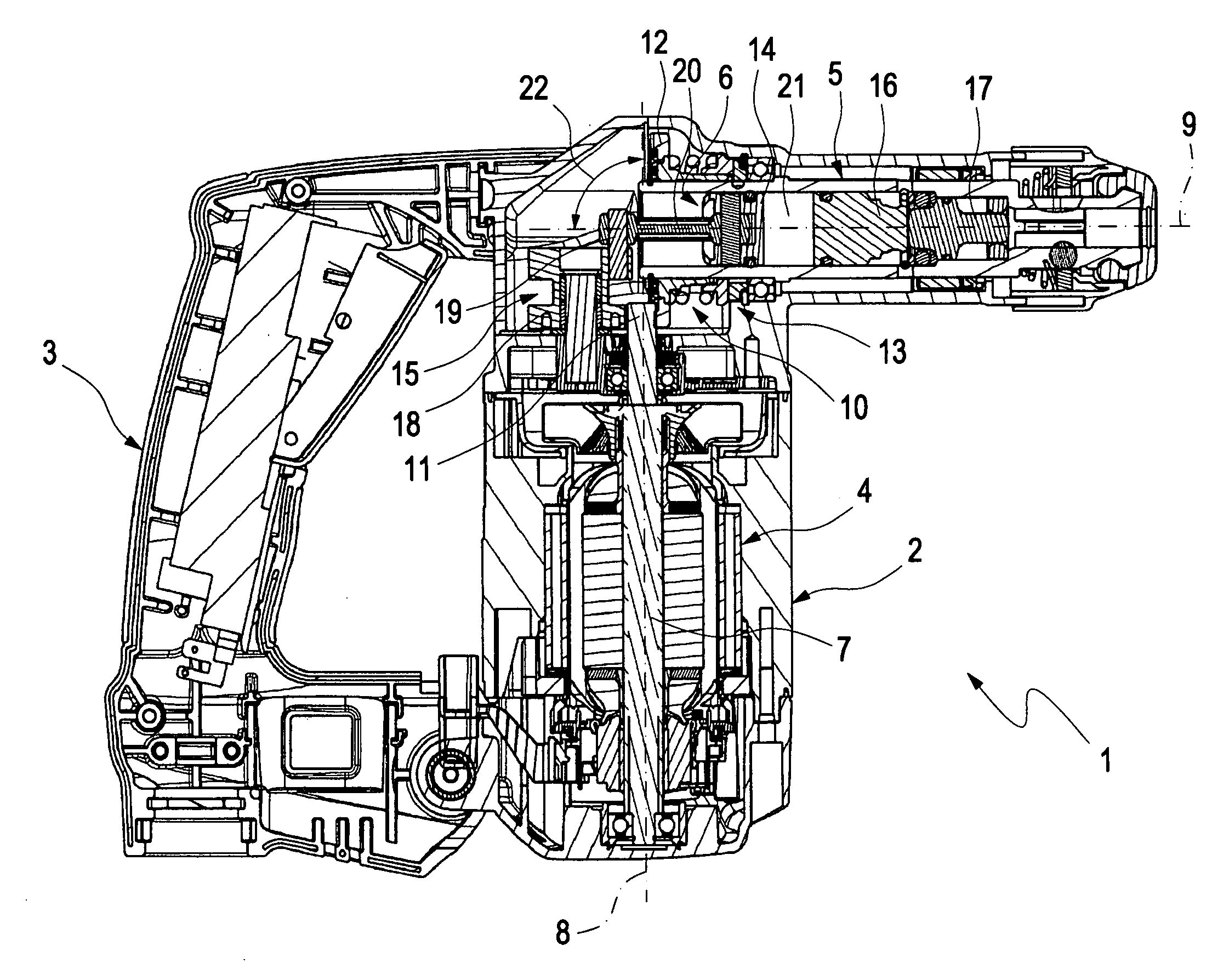
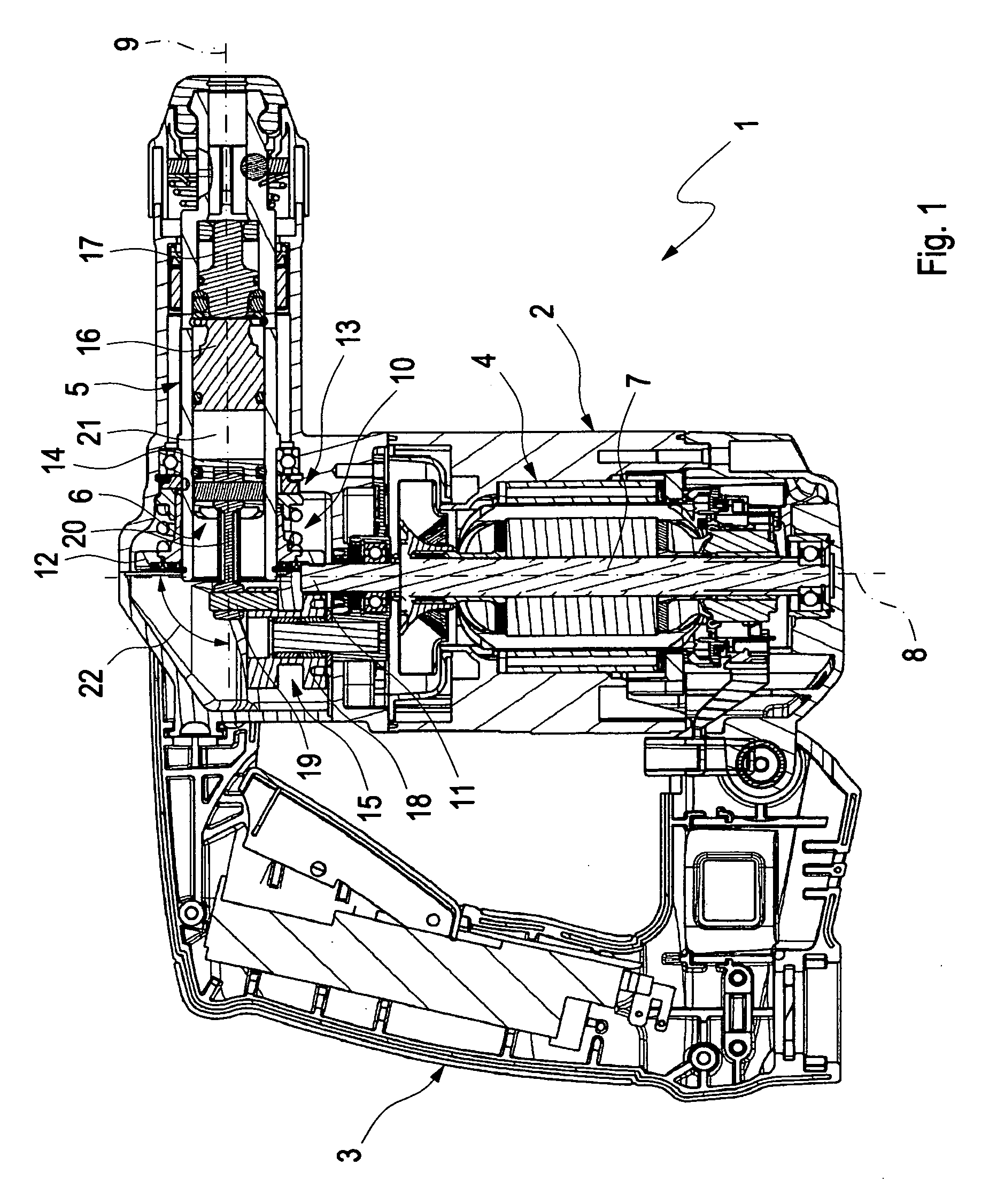
[0013]As shown in FIG. 1, a hammer drill 1 intended for manually-guided operation includes a housing 2, which may optionally have a handle 3. Housing 2 of hammer drill 1 holds an electric drive motor 4 as well as a tool spindle 5 and a pneumatic hammer function 6. Drive motor 4 is equipped with a drive shaft 7, which rotates about a shaft axis 8 when hammer drill 1 is operated. Drive motor 4 drives tool spindle 5 in a rotary manner about a spindle axis 9. For this purpose, in the example shown, drive motor 4 is coupled in a driving manner with tool spindle 5 via a spindle gear mechanism 10. For these purposes, spindle gear mechanism 10 is preferably a single-stage gear mechanism, via which tool spindle 5 is driven directly by drive shaft 7. Spindle gear mechanism 10 is preferably configured as an angular gear mechanism and accordingly has a pinion gear 11 attached to or conformed on drive shaft 7, which pinion gear is in engagement with a ring gear 12 that serves to transfer turning...


PUM

PropertyMeasurementUnit
Angleaaaaaaaaaa
Angleaaaaaaaaaa
Angleaaaaaaaaaa

Abstract

A hammer drill for manually guided operation includes an electric drive motor, a tool spindle and a pneumatic hammer function. The hammer drill includes a pressure piston, a striker, and a beat piece for striking axially against a tool that is held by the tool spindle. When the striker reaches a forward limit position, an end section thereof protrudes into a retaining ring that is aligned coaxially with the spindle axis. Manufacturing quality can be improved by bracing the retaining ring against an annular collar in the tool spindle on the one side and axially against a locking ring set in an annular groove conformed in the tool spindle via a retaining disc on the other side. The retaining ring, the retaining disc and the non-return disc are each mirror-symmetrical.

Description

REFERENCE TO RELATED APPLICATION[0001]This application claims priority to German Patent Application No. 102008022454.5-14 filed May 8, 2008.BACKGROUND OF THE INVENTION[0002]The present invention relates to a hammer drill for manually guided operation.[0003]A hammer drill that is intended for manually guided operation normally includes an electric drive motor, a tool spindle that can be driven about a spindle axis, and a pneumatic hammer function. A hammer drill of such kind is known from German patent number DE 10 2006 054 288 filed of Nov. 17, 2006. In this hammer drill, the pneumatic hammer function has a pressure piston disposed in the tool spindle that is displaceable in reciprocating linear fashion, a striker located in the tool spindle that is actuated pneumatically by the pressure piston, and a beat piece located in the tool spindle that may be propelled by the striker to strike axially against a tool that is held by the tool spindle. The hammer function further includes a re...

Claims


Application Information

Patent Timeline
IPC IPC(8): B25D11/06B25D16/00B23B45/16
CPCB25D11/005B25D11/125B25D17/06B25D17/24B25D2250/191B25D2216/0023B25D2222/21B25D2222/57B25D2250/065B25D2211/003
Inventor ROELFS, ANDREASKUMPF, RAINER
Owner AEG ELECTRIC TOOLS
Why Eureka
Try Eureka