
Modular hybrid drill bit

a hybrid drill bit and module technology, applied in drill bits, earth drilling and mining, cutting machines, etc., can solve the problems of cutter stopping rotation, bearing failure, rolling cutter bit failure,

Inactive Publication Date: 2009-11-05
BAKER HUGHES INC
View PDF99 Cites 59 Cited by
  • Summary
  • Abstract
  • Description
  • Claims
  • Application Information

AI Technical Summary

Benefits of technology

The present invention provides an improved hybrid earth-boring bit with a bit body, fixed blade, axial slot, and rolling cutter. The bit leg is secured in the slot with a fastener and can be adjusted for different drilling conditions. The slot is formed by three sides with an acute angle. The bit body has a cylindrical receptacle and a bit body portion secured together by welding. The bit also includes a nozzle, bearing, and lubricant compensator. The technical effects of the invention are improved drilling efficiency, stability, and durability of the bit.

Problems solved by technology

Rolling-cutter bits tend to fail when the bearing or seal fails and one or more cutters stop rotating or rotating easily.
Bearing failure is most often caused by loss of lubricant from the bit or damage to the bearing as a result of severe operating conditions.
In some cases, the bearing failure is so catastrophic that a cutter falls off of the bearing, which can lead to costly and time-consuming fishing operations to recover the lost cutter.
Typically, rolling-cutter bits cannot successfully be refurbished because of irreparable bearing damage.
Instead, individual diamond cutters tend to be lost and the bit body is slowly worn away such that it is no longer within drilling specifications.

Method used


Image

  • Modular hybrid drill bit
  • Modular hybrid drill bit
  • Modular hybrid drill bit

Examples


Embodiment Construction

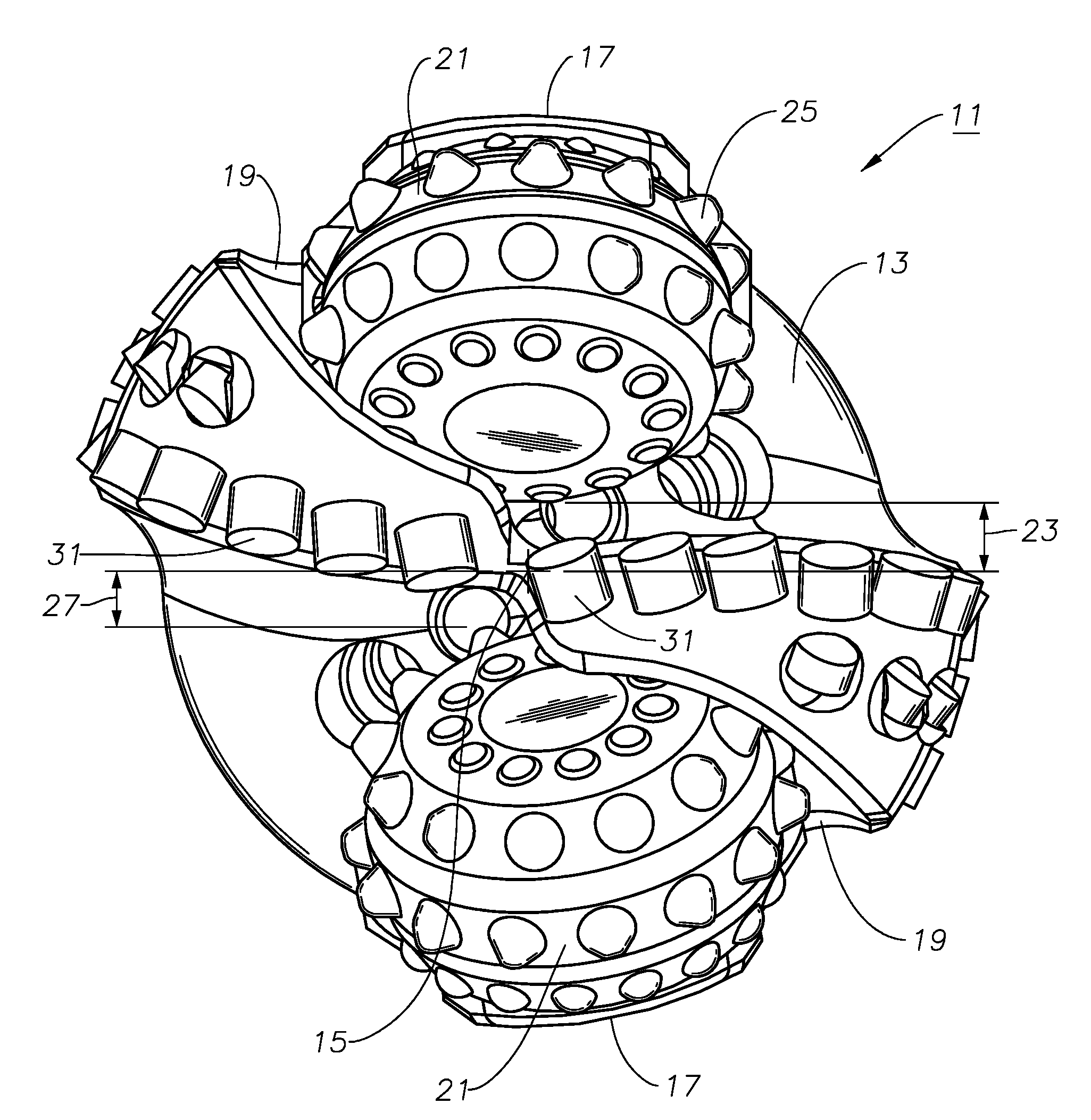
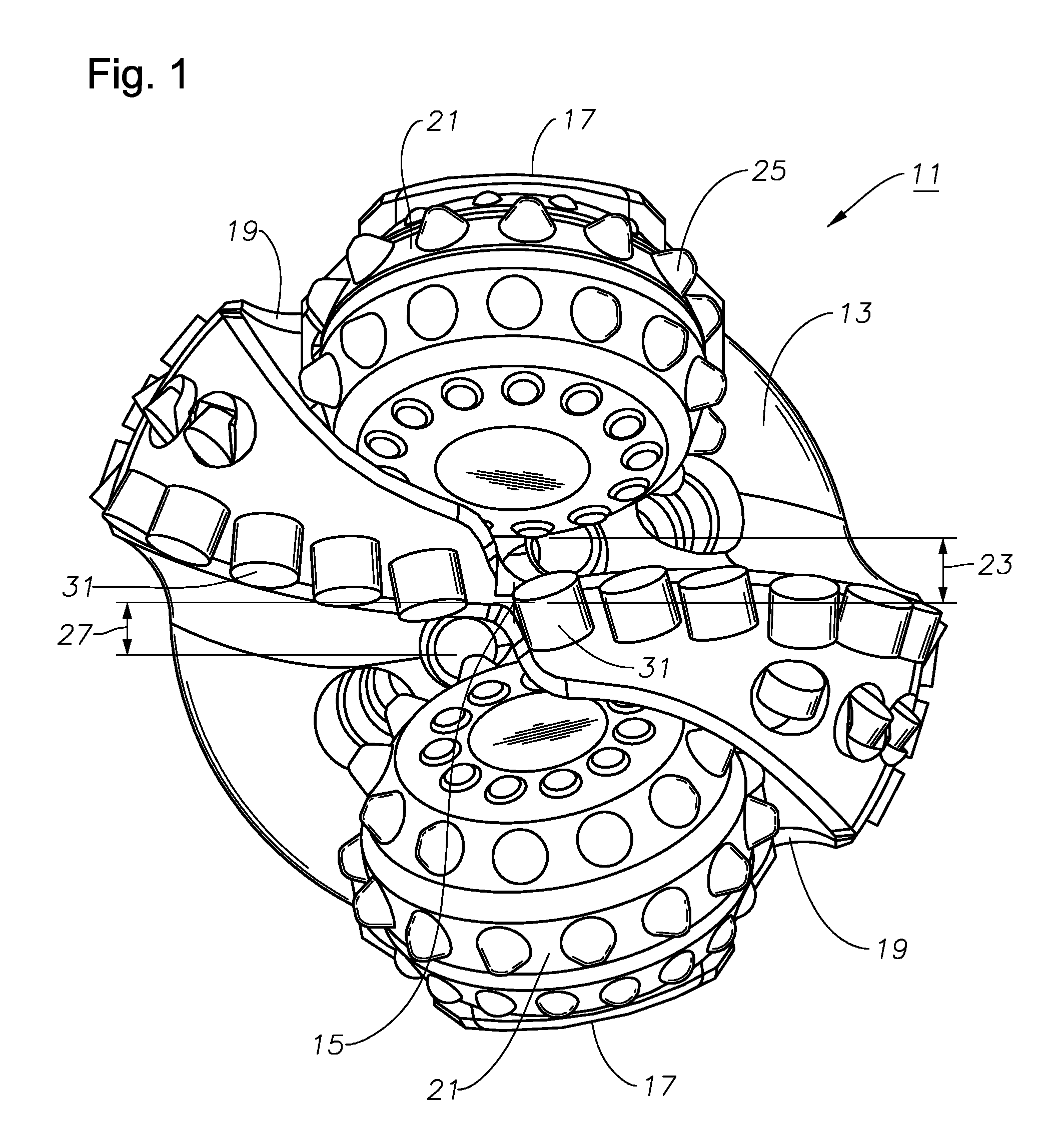
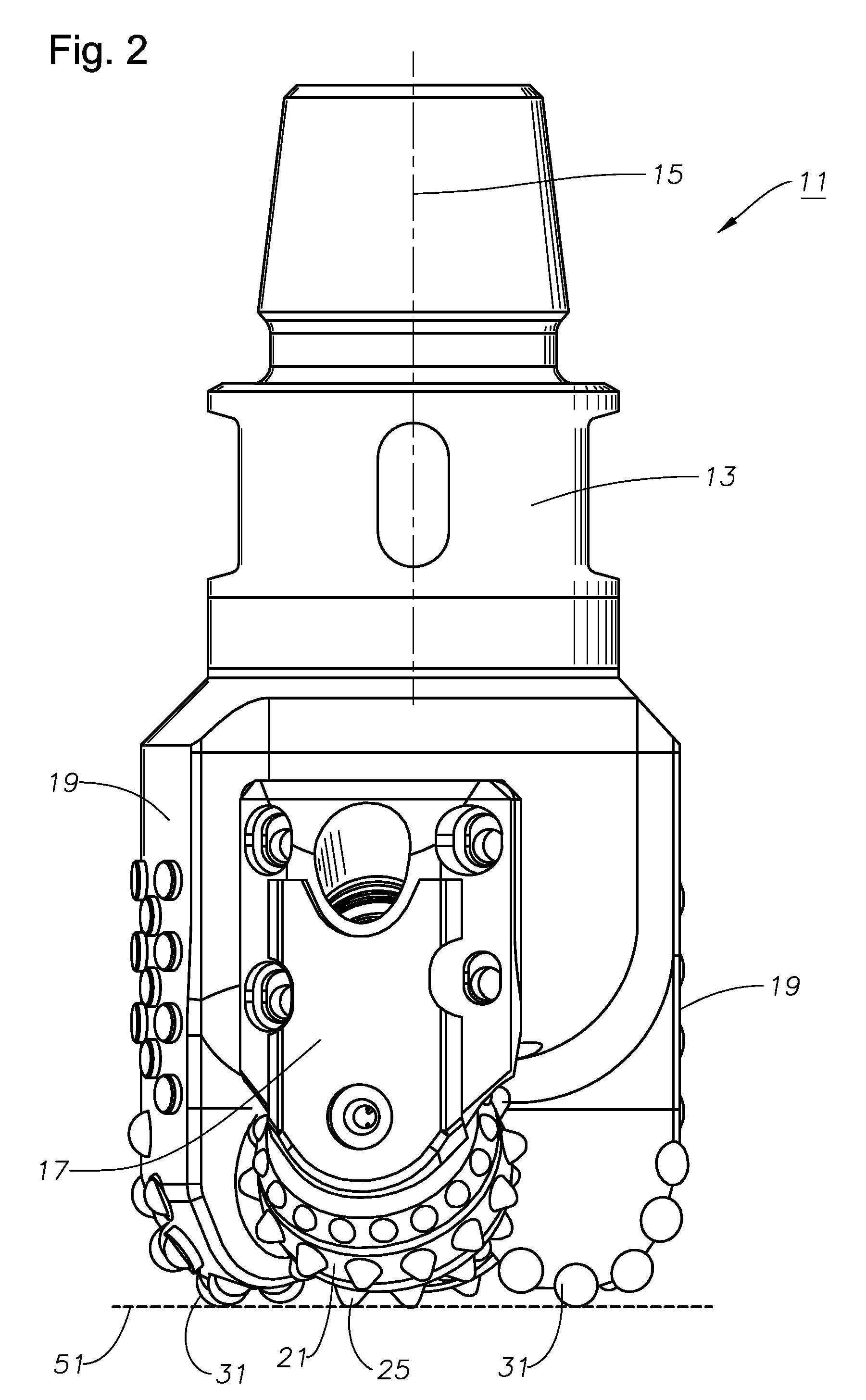
[0021]Referring to FIGS. 1-2, an illustrative embodiment of a modular hybrid earth-boring drill bit is disclosed. The bit 11 comprises a bit body 13 having an axis 15 that defines an axial center of the bit body 13. A plurality (e.g., two shown) of bit legs or heads 17 extend from the bit body 13 in the axial direction. The bit body 13 also has a plurality (e.g., also two shown) of fixed blades 19 that extend in the axial direction. The number of each of legs 17 and fixed blades 19 is at least one but may be more than two (as in the case of the embodiment illustrated in FIG. 3). In one embodiment, the centers of the legs 17 and fixed blades 19 are symmetrically spaced apart from each other about the axis 15 in an alternating configuration.

[0022]Rolling cutters 21 are mounted to respective ones of the bit legs 17. Each of the rolling cutters 21 is shaped and located such that every surface of the rolling cutters 21 is radially spaced apart from the axial center 15 (FIG. 2) by a minim...


PUM

PropertyMeasurementUnit
included angleaaaaaaaaaa
acute angleaaaaaaaaaa

Abstract

An earth-boring bit comprising a bit body is cofigured at its upper end for connection into a drillstring. A fixed blade depends axially downwardly from the bit body. An axially extending slot is formed in the bit body adjacent the fixed blade. A bit leg is received and retained in the slot by engagement between the slot and correspondingly shaped bit leg, wherein the bit leg cannot be removed from the slot except by axial movement relative to the bit body. A rolling cutter is secured to the bit leg at its lower extent. A fastener secures the bit leg against movement relative to the bit body and extends through oblong apertures in the bit leg and into the bit body, wherein the bit leg can be moved axially relative to the bit body to adjust the projection of the rolling cutter relative to the fixed blade. The slot defines a pair of generally opposed sides connected by a third side, the generally opposed sides being inclined toward one another to define a dovetail that corresponds with the shape of the bit leg. The bit body further comprises a shank that is configured for connection into the drillstring at its upper extent and has a generally cylindrical receptacle formed in its lower extent; and a bit body portion having a generally cylindrical upper extent, the receptacle being and dimensioned to receive the upper extent of the bit body, wherein the shank and bit body portions are secured together by welding.

Description

BACKGROUND OF THE INVENTION[0001]1. Technical Field[0002]The present invention relates in general to earth-boring drill bits and, in particular, to a bit having a combination of rolling and fixed cutters and cutting elements and a method of drilling with same.[0003]2. Description of the Related Art[0004]The success of rotary drilling enabled the discovery of deep oil and gas reservoirs and production of enormous quantities of oil. The rotary rock bit was an important invention that made the success of rotary drilling possible. Only soft earthen formations could be penetrated commercially with the earlier drag bit and cable tool, but the two-cone rock bit, invented by Howard R. Hughes, U.S. Pat. No. 930,759, drilled the caprock at the Spindletop field, near Beaumont, Tex. with relative ease. That venerable invention, within the first decade of the last century, could drill a scant fraction of the depth and speed of the modern rotary rock bit. The original Hughes bit drilled for hours...

Claims


Application Information

Patent Timeline
Patent Type & Authority Applications(United States)
IPC IPC(8): E21B10/08
CPCE21B10/14E21B10/24Y10T29/49963Y10T29/49947Y10T29/49948E21B10/62
Inventor MCCORMICK, RON D.PESSIER, RUDOLF CARLNGUYEN, DON Q.MARVEL, TIM KINGISBELL, MATTHEW R.ZAHRADNIK, ANTON F.CEPEDA, KARLOS B.DAMSCHEN, MICHAEL STEVENWINNON, STEVE M.
Owner BAKER HUGHES INC
Learn More