
Use of disk surface for electroporation of adherent cells

a technology of adherent cells and disk surfaces, applied in specific use of bioreactors/fermenters, biomass after-treatment, biochemistry apparatus and processes, etc., can solve the problems of elusive and high efficiency, and achieve the effect of convenient removal, improved cell access, and flexible and efficient procedures

Inactive Publication Date: 2009-10-29
BIO RAD LAB INC
View PDF18 Cites 4 Cited by
  • Summary
  • Abstract
  • Description
  • Claims
  • Application Information

AI Technical Summary

Benefits of technology

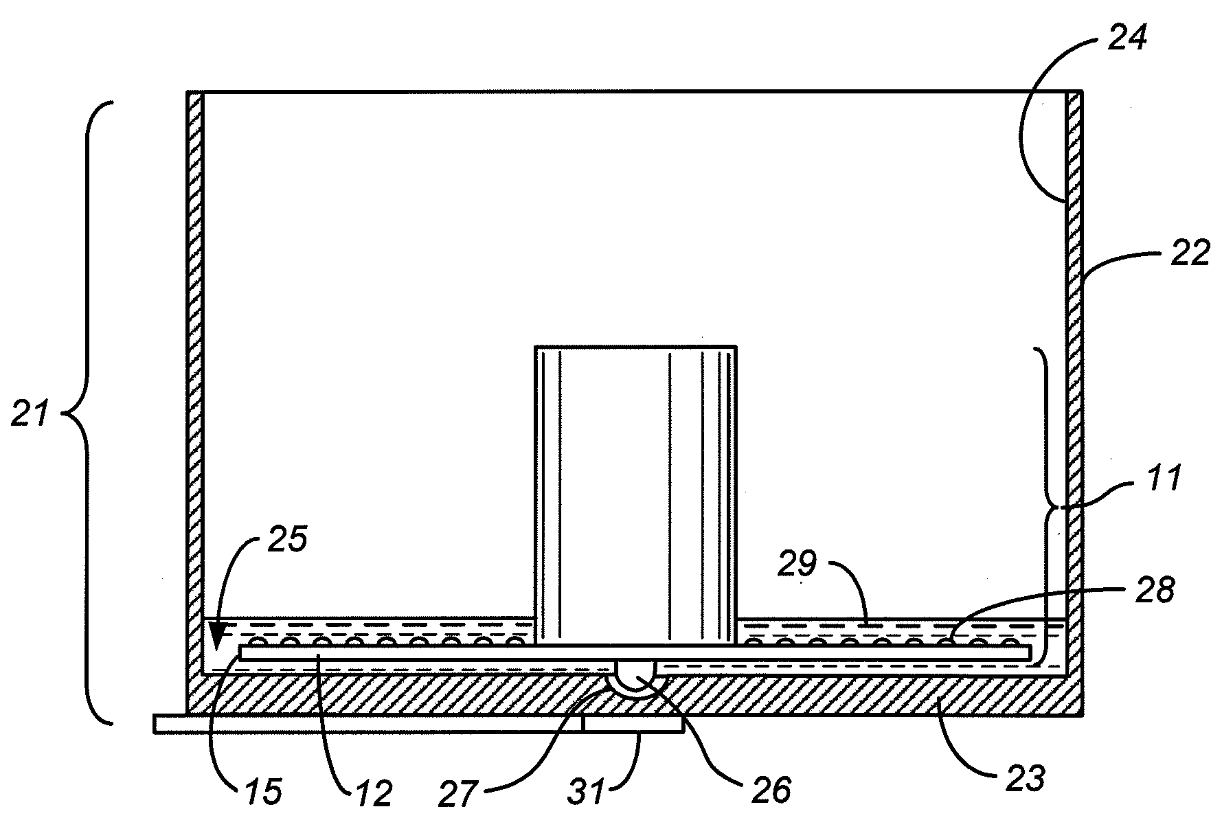
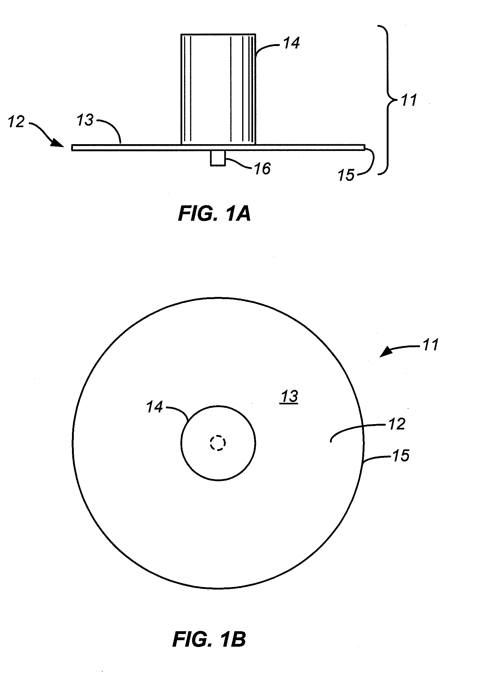
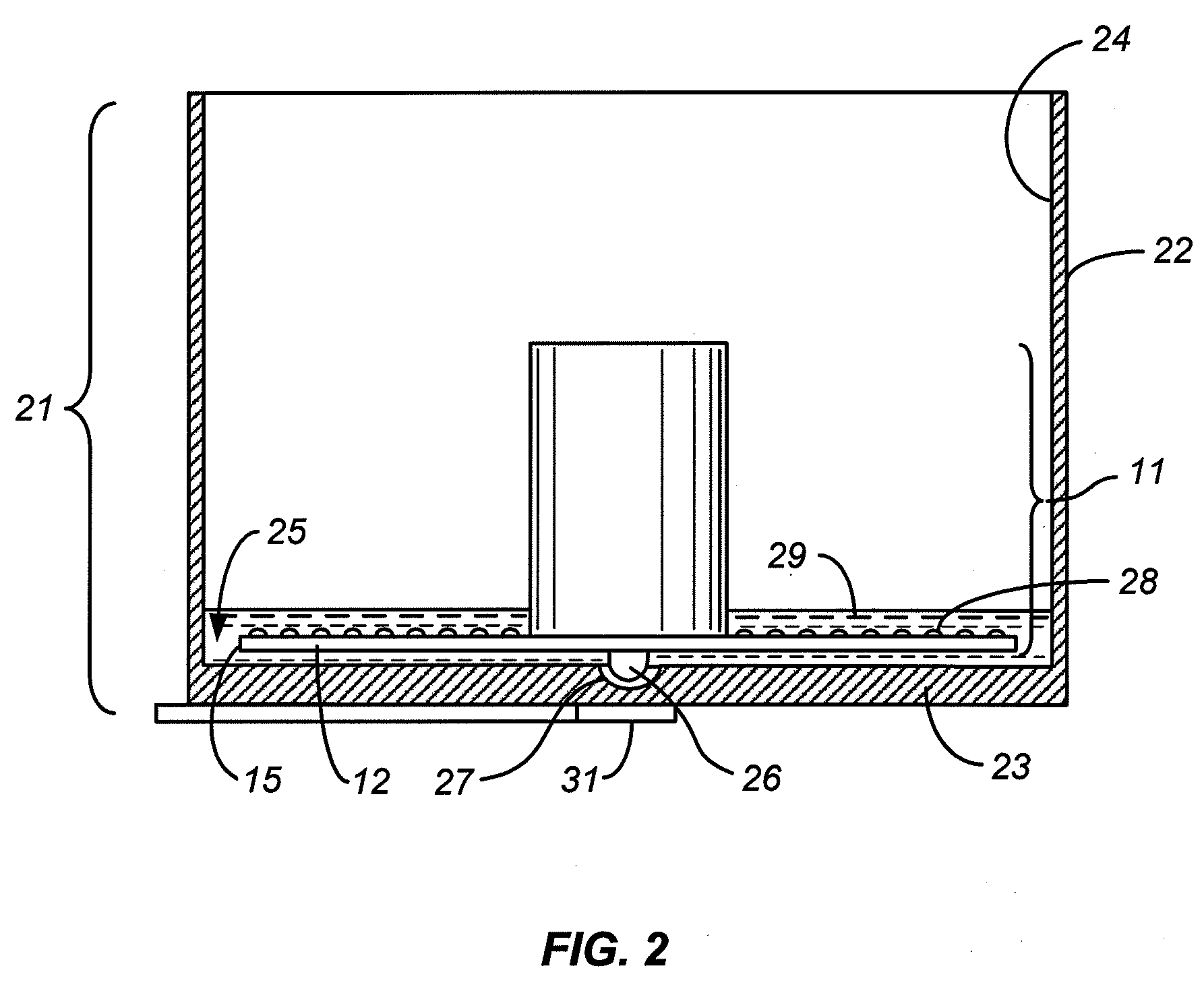
[0018]The inner electrode material resides on an outward-facing surface of a cylindrical support, and in certain embodiments of the invention, the disk and this cylindrical support with the inner electrode(s) on its surface are rigidly joined to form a unitary member. In other embodiments, the disk and the inner cylinder are separate components of the apparatus allowing cells to be grown on the disk surface without the presence of the inner cylinder. Regardless of whether the disk is integrated with the inner cylinder or separate, it is preferred that the disk be readily removable from the outer cylinder so that cells can be grown on the disk surface outside the apparatus. A disk that is removable from the outer cylinder offers flexibility and efficiency to the procedure by allowing cells to be grown on, or otherwise adhered to, one disk while cells on another disk are being subjected to electroporation. The disk can be placed in a vessel that allows the disk, or two or more disks, to be rotated while cells are being grown on its surface. The rotation agitates the surrounding growth medium and thereby improves access of the cells to the nutrients in the medium and to gases that promote cell growth. In certain embodiments of the invention, the disk can also be rotated inside the electroporation chamber (i.e., the outer cylinder) during electroporation.

Problems solved by technology

Achieving high efficiency is a continuing challenge in all forms of electroporation, but even more so in the electroporation of adherent cells.
While the documents in the above list present a variety of approaches to improving the efficiency and uniformity of transfection, these qualities remain elusive and are a continuing goal.

Method used


Image

  • Use of disk surface for electroporation of adherent cells
  • Use of disk surface for electroporation of adherent cells
  • Use of disk surface for electroporation of adherent cells

Examples


Embodiment Construction

[0028]This invention is not restricted to disks of any particular size or size range. Preferably, however, the width of the ring-shaped area between the two cylindrical surfaces and on which the adherent cells reside is preferably small compared to the outer diameter of the disk so that the intensity of the electrical field created by the electrodes varies only minimally in the radial direction across the cell area when the electrodes fully extend around the circumferences of their respective cylinders. With a disk and electrodes of this shape, all cells adhering to the disk surface will experience a field intensity that is close to being uniform, or at least one that will not include a steep gradient in regions toward the center of the disk. With these considerations in mind, the ratio of the diameter of the inner edge to the diameter of the outer edge is preferably within the range of about 0.2 to about 0.95, more preferably the range of about 0.3 to about 0.9, and most preferably...


PUM

PropertyMeasurementUnit
Diameteraaaaaaaaaa
Electric potential / voltageaaaaaaaaaa
Responsivityaaaaaaaaaa

Abstract

Adherent cells on the surface of a disk are transfected by electroporation between coaxial circular cylinders with electrodes on the opposing surfaces on either side of the annular space between the cylinders by placing a buffer solution containing the transfecting species in the annular space over the cell and applying an electric potential between the electrodes.

Description

CROSS-REFERENCE TO RELATED APPLICATION[0001]This application claims the benefit of U.S. Provisional Patent Application No. 61 / 047,637, filed Apr. 24, 2008, the contents of which are incorporated herein by reference.BACKGROUND OF THE INVENTION[0002]1. Field of the Invention[0003]This invention lies in the field of transfection, the process by which exogenous molecular species are inserted into membranous structures by rendering the membrane permeable on a transient basis while the structures are in contact with a liquid solution of the species, thereby allowing the species to pass through the membrane, and doing so in such a manner that the structures resume their viability after the procedure is complete.[0004]2. Description of the Prior Art[0005]The introduction of exogenous species, including hydrophilic or membrane-impermeant species, into biological cells is of use in certain biologic and biochemical techniques. A high efficiency transfection is one in which the exogenous specie...

Claims


Application Information

Patent Timeline
IPC IPC(8): C12N15/87C12M1/42
CPCC12M25/06C12N15/87C12M35/02
Inventor RAGSDALE, CHARLES W.
Owner BIO RAD LAB INC
Learn More