Liquid crystal display

Active Publication Date: 2009-10-29
TSINGHUA UNIV +1
View PDF9 Cites 5 Cited by
  • Summary
  • Abstract
  • Description
  • Claims
  • Application Information

AI Technical Summary

Benefits of technology

[0047]The liquid crystal display in the present embodiment has the many advantages including the following. Firstly, the carbon nanotube structure can be used as a heating layer, thus the liquid crystal display can perform at low external temperatures. Secondly, the carbon nanotube structure can be used as a heating layer and an alignment layer at the same time, thus simplify the structure of the liquid crystal display and reduce the thickness of the liquid crystal display. Thirdly, the carbon nanotube structure can act as both an alignment layer and an electrode layer, thus further simplify the structure of the liquid crystal display and reduce the thickness of the liquid crystal display. Therefore, the liquid crystal display has improved durability and improved arrangement of liquid crystal molecules.

Problems solved by technology

However, for many reasons, the liquid crystal display cannot perform at low temperature environment.
Secondly, the viscosity of the liquid crystal molecules in the liquid crystal layer will increase as the external temperature decreases.
However, the indium-tin oxide transparent conductive layer is not very efficient for heating and consumes space, which requires that the liquid crystal display be thicker.

Method used


Image

  • Liquid crystal display
  • Liquid crystal display
  • Liquid crystal display

Examples


Embodiment Construction

[0020]References will now be made to the drawings to describe, in detail, various embodiments of the present liquid crystal display.

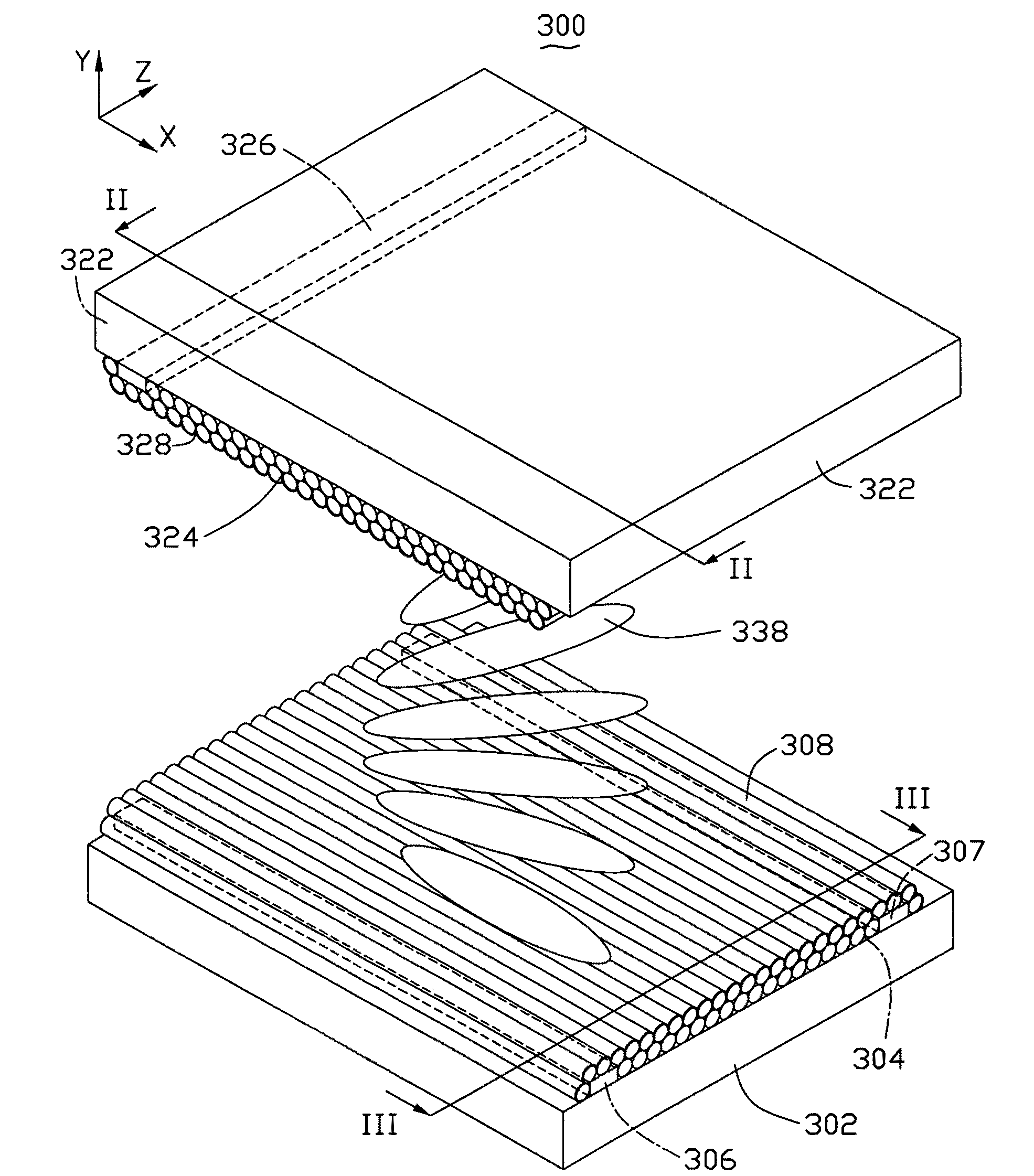
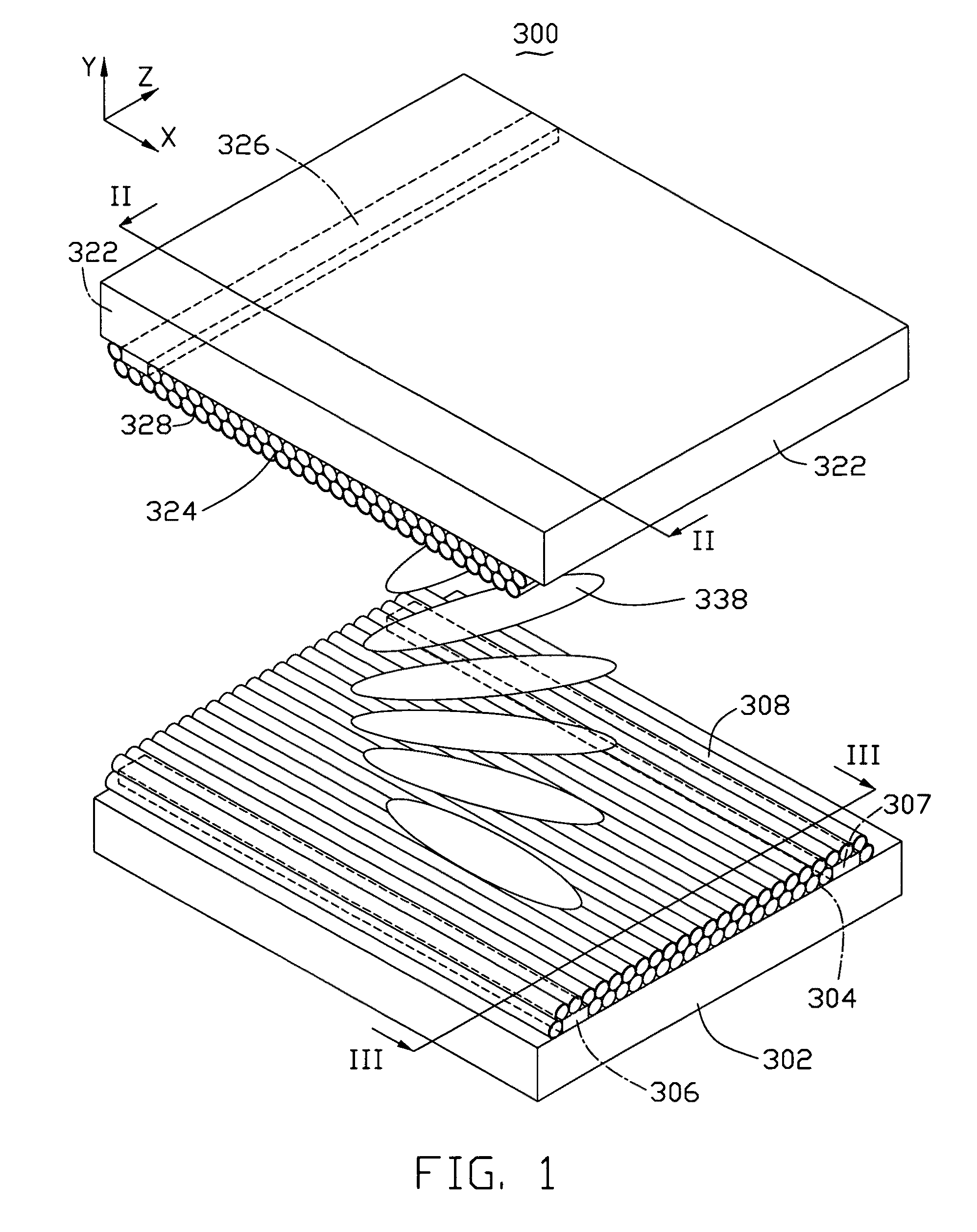
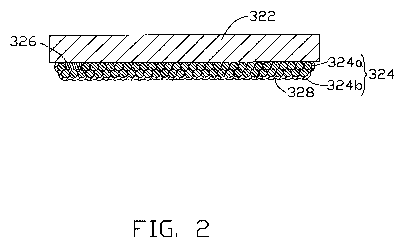
[0021]Referring to FIGS. 1, 2, and 3, a liquid crystal display 300 in the first embodiment includes a first substrate 302, a first alignment layer 304, a liquid crystal layer 338, a second alignment layer 324, and a second substrate 322. The liquid crystal layer 338 is sandwiched between the first substrate 302 and the second substrate 322. The first alignment layer 304 is located on the first substrate 302 adjacent to the liquid crystal layer 338. A plurality of parallel first grooves 308 is defined in a surface of the first alignment layer 304 facing the liquid crystal layer 338. The second alignment layer 324 is located on the second substrate 322 adjacent to the liquid crystal layer 338. A plurality of parallel second grooves 328 is defined in a surface of the second alignment layer 324 facing the liquid crystal layer 338. An alignment direction of ...


PUM


Abstract

A liquid crystal display includes a first substrate, a first alignment layer, a liquid crystal layer, a second alignment layer, and a second substrate opposite to the first substrate, a first electrode and a second electrode. The liquid crystal layer is sandwiched between the first substrate and the second substrate. The first alignment layer is located on the first substrate and face the liquid crystal layer. The second alignment layer is located on the second substrate and face the liquid crystal layer. Furthermore, at least one of the first and second alignment layers comprises a carbon nanotube structure, and the carbon nanotube structure is electrically connected to the first electrode and the second electrode.

Description

RELATED APPLICATIONS[0001]This application is related to applications entitled “LIQUID CRYSTAL DISPLAY”, filed ______ (Atty. Docket No. US19075); “LIQUID CRYSTAL DISPLAY”, filed ______ (Atty. Docket No. US21521). The disclosures of the above-identified applications are incorporated herein by reference. The application is also related to co-pending applications entitled “LIQUID CRYSTAL DISPLAY SCREEN”, filed Nov. 20, 2008 (Atty. Docket No. US18573); “LIQUID CRYSTAL DISPLAY SCREEN”, filed Nov. 20, 2008 (Atty. Docket No. US18574); “METHOD FOR MAKING LIQUID CRYSTAL DISPLAY SCREEN”, filed Nov. 20, 2008 (Atty. Docket No. US18575); “LIQUID CRYSTAL DISPLAY SCREEN”, filed Nov. 20, 2008 (Atty. Docket No. US19048); “LIQUID CRYSTAL DISPLAY SCREEN”, filed Nov. 20, 2008 (Atty. Docket No. US19049); and “LIQUID CRYSTAL DISPLAY SCREEN”, filed Nov. 20, 2008 (Atty. Docket No. US19050); “METHOD FOR MAKING LIQUID CRYSTAL DISPLAY SCREEN”, filed Nov. 20, 2008 (Atty. Docket No. US19051).BACKGROUND[0002]1. ...

Claims


Application Information

Patent Timeline
IPC IPC(8): G02F1/1337
CPCG02F2202/36G02F1/1337
Inventor LIU, LIANGJIANG, KAI-LIFU, WEI-QIFAN, SHOU-SHAN
Owner TSINGHUA UNIV
Why Eureka
Try Eureka