
Shallow Water Boat

a water boat and water body technology, applied in the field of boats, can solve the problems of long time and efficiencies for traveling to and from various fishing points, and the design as shown in white still has problems, and achieve the effect of improving efficiency

Inactive Publication Date: 2009-10-22
PRO LINENEW WATER
View PDF1 Cites 0 Cited by
  • Summary
  • Abstract
  • Description
  • Claims
  • Application Information

AI Technical Summary

Benefits of technology

[0008]It is an object of the present invention to provide a shallow water boat that will operate efficiently in deep water.
[0009]It is another object of the present invention to provide a shallow water boat that is maneuverable in shallow water, yet handles well in deep and open water.
[0011]It is still another object of the present invention to provide a shallow water boat with a tunnel that starts at approximately the amidship location in the hull with an unplugable openings at the beginning of the tunnel to cause separation between the water and the tunnel when operating in water.
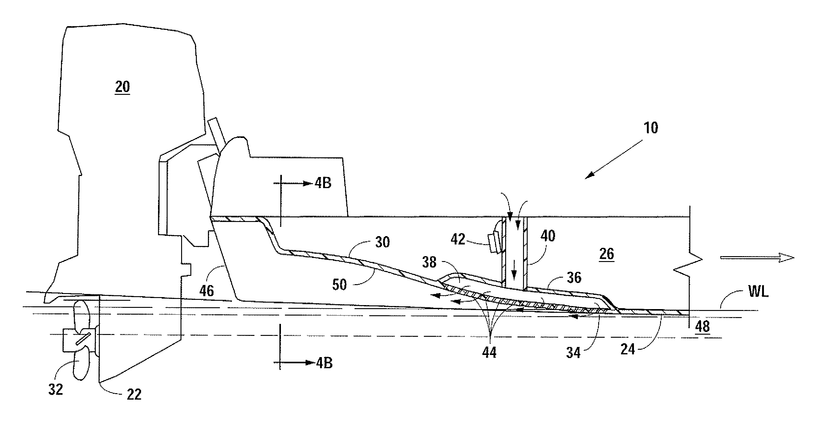
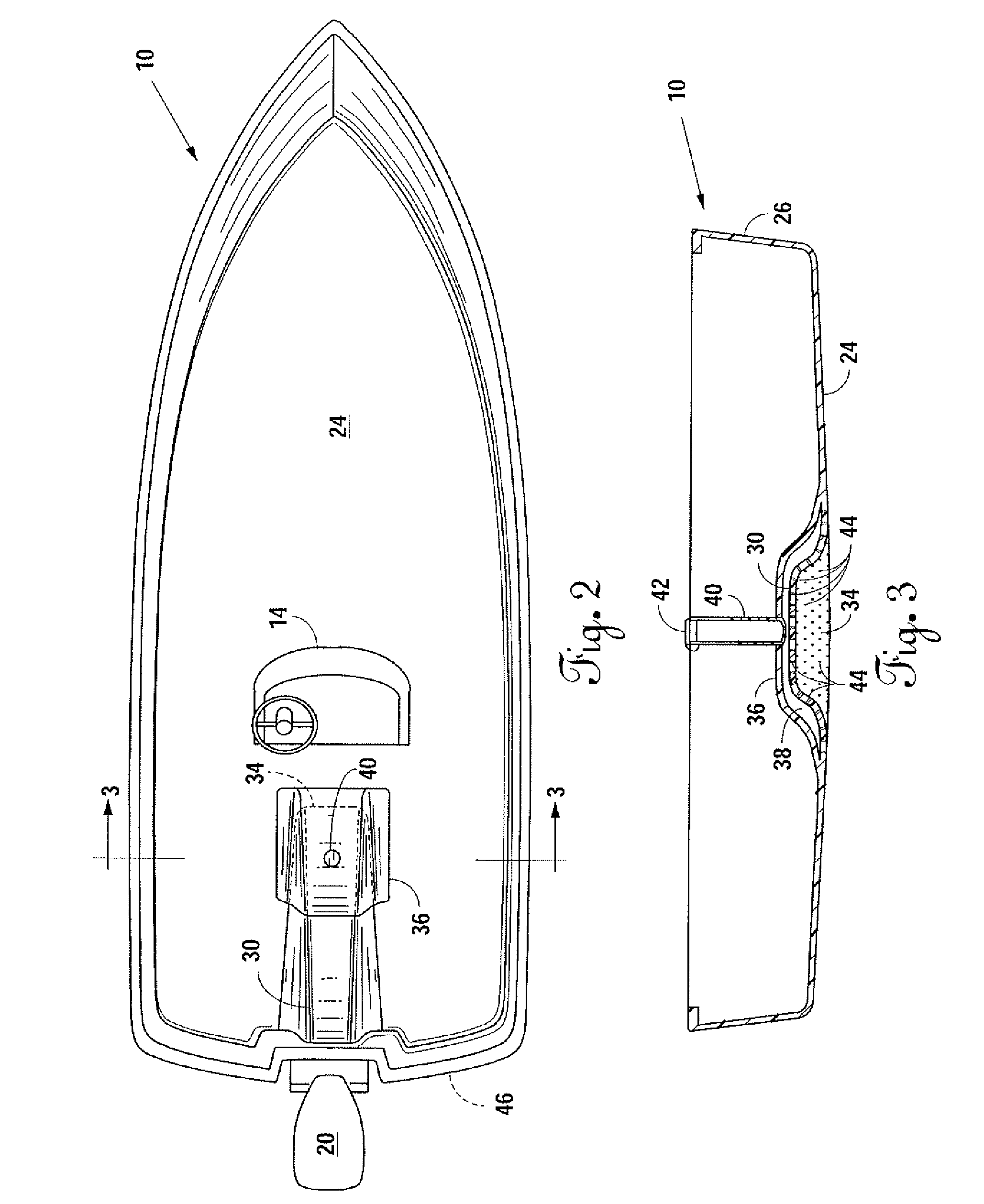
[0012]It is a further object of the present invention to provide a tunnel in the hull of a flat bottom boat for use in shallow water, which tunnel starts at the amidship location and has a slight S shape top therein. At the beginning of the tunnel, a plenum connects through a series of holes to allow air to be drawn through venturi action into the beginning of the tunnel, which air causes a separation between water moving into the tunnel and the tunnel. The plenum may be connected (or disconnected) to a source of air. When the plenum is connected to a source of air, due to the venturi suction, air is drawn into the tunnel rather than water. This allows the boat to be operated more efficiently in open water, at which point the motor will be lowered down into the water below the bottom of the boat. However, when the plenum is not connected to a source of air, surface tension draws water moving across the bottom of the boat up into the tunnel. Because the tunnel is located in the center of the boat, the aft end of the boat and tunnel terminate in front of the propeller for the motor. The motor may be raised up above the bottom of the boat, but the propeller still strikes the water that is drawn through the tunnel. In this manner, the boat can operate and maneuver in very shallow water without the propeller or motor extending below the hull of the boat.
[0013]It helps to have a proliferation of holes connecting through the hull of the boat from the plenum to the beginning of the tunnel so that a complete separation of the water from the tunnel is accomplished when operating in deep water. Also, having a slight S curve in the top of tunnel further insures the complete separation of water from the tunnel. This allows the motor and propeller to be lowered down into the water when operating in open water, but raise when operating in shallow water. Also, the tunnel is not a traditional V-shape, but has a flat upper surface with rounded corners. The flat upper surface has the slight S shape to (1.) insure complete separation of water from the tunnel when connected to a source of air, but (2.) stay attached in laminar flow fashion when not connected to a source of air.

Problems solved by technology

However, getting to and from the good fishing areas from a suitable dock or put in location normally requires traveling some distance over open water.
If the boat is designed entirely for shallow waters the time and efficiencies for traveling to and from various fishing points can be long and expensive.
However, the design as shown in White still has problems.
The straight and enlarging design of the tunnel also does not induce separation of the water from the tunnel when operating at high speeds in deep water.

Method used


Image

  • Shallow Water Boat
  • Shallow Water Boat
  • Shallow Water Boat

Examples


Embodiment Construction

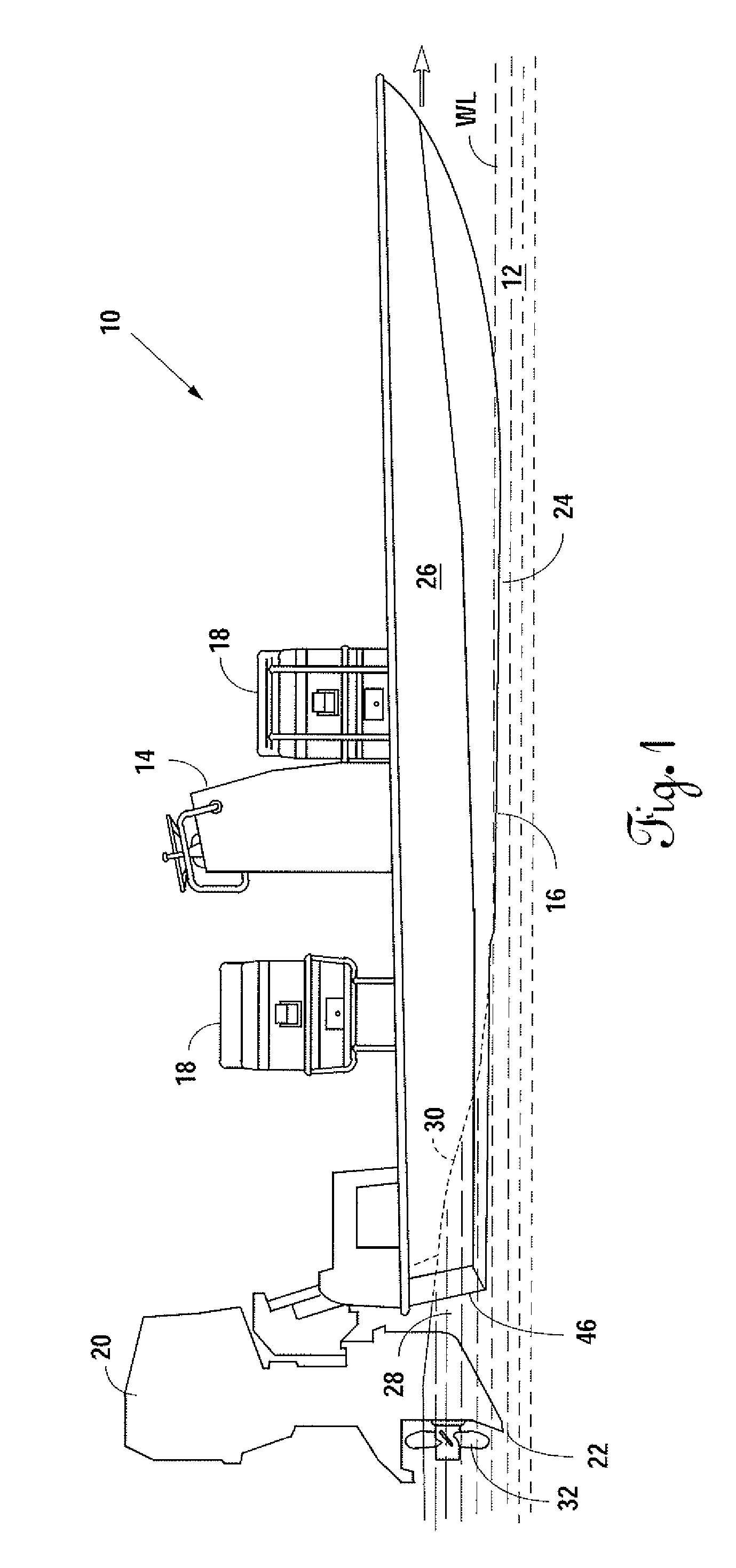
[0025]Referring to FIG. 1 of the drawings, a shallow draft boat 10 is shown in shallow water 12 that has a water line WL as the boat moves forward in the direction indicated by the arrow. The shallow draft boat 10 has the helm 14 mounted at approximately amidship 16 on the deck (not shown) of the shallow draft boat 10. Seating 18 is also provided on the deck (not shown) of the shallow draft boat 10.

[0026]In the view as shown in FIG. 1, the outboard motor 20 is in a raised position so that the lower portion 22 of the outboard motor 20 is approximately level with the bottom 24 of the hull 26 of the shallow draft boat 10. As the shallow draft boat 10 moves forward, a ridge 28 of water follows a tunnel 30 in a matter described hereinbelow to strike the propeller 32 of the outboard motor 20. The spinning of the propeller 32 in the ridge 28 of the shallow water 12 provides the forward motion for the shallow draft boat 10.

[0027]Referring now to FIG. 2 and 3 in combination, the shallow draf...


PUM


Abstract

A shallow water boat is shown that operates well in both shallow water and deep water. A tunnel is provided along a centerline of a flat bottom, which tunnel starts near amidships increases in depth and terminates at the aft of the shallow water boat. A top of the tunnel has an S curve therein. A front end of the tunnel connects through a series of angled holes into a plenum via a conduit to atmosphere above the maximum water line of the shallow water boat. During shallow water operation, the motor is raised and the conduit is plugged so water flows through the tunnel to the propeller for the motor. During deep water operation, the motor is lowered and the conduit unplugged so that water does not flow through the tunnel.

Description

BACKGROUND OF THE INVENTION[0001]1. Field of the Invention[0002]This invention relates generally to boats and, more specifically, to a boat for alternatively operating in shallow water or at high speeds in deep water.[0003]2. Background of the Prior Art[0004]Various types of boats, ships or vessels have been used from the earliest recorded history of man. Different type boats have different functions. One boat may be designed for speed and another boat designed for hauling heavy loads. Likewise, boats may be designed for operation in shallow water versus deep water or in the ocean. Some boats are designed for maneuverability and others are designed for holding a straight line.[0005]Fishing, whether as sport or as a means of making a living, is very popular throughout the world. While fishing can be performed from the banks, the best fishing is normally performed from boats operated either near the shore or in shallow water of bays or marshes which would normally have fish. To operat...

Claims


Application Information

Patent Timeline
IPC IPC(8): B63H20/02
CPCB63B1/042B63B1/38Y02T70/122B63H5/16B63H20/10B63H1/28Y02T70/10
Inventor CLANCEY, TIMOTHY L.
Owner PRO LINENEW WATER
Learn More