
Power tool

a power tool and power technology, applied in the field of power tools, can solve the problems of clogging the guard on the conventional edger with dirt and grass, occupying too much occupying a lot of storage space for existing devices, etc., and achieve the effect of less spa

Inactive Publication Date: 2009-10-15
PRIZM INT
View PDF50 Cites 16 Cited by
  • Summary
  • Abstract
  • Description
  • Claims
  • Application Information

AI Technical Summary

Benefits of technology

[0010]The technology described herein incorporates a pivoting shaft which swings to a relatively vertical position so that the edger occupies less space. The technology described herein incorporates a guard that can be removed completely from the edger for clean out by pushing a release button. This guard also incorporates a safety interlock that prevents operation of the motor and blade when the guard is removed. The technology described herein uses a spring lever to detent in various positions to adjust depth. The wheel of the lawn edger also has an additional position that lifts the unit enough so that the edging guide does not contact the ground while moving the lawn edger to its storage location.
[0011]In an exemplary embodiment the technology described herein is a motorized lawn edger incorporating a pivoting shaft for compact storage, a removable blade guard for easy clean out and an easily adjustable front wheel for convenient edging depth adjustment.
[0012]The motorized lawn edger has a folding shaft. The blade guard is completely removeable instead of being hinged. The adjustable front wheel responds quickly and is more convenient to operate than existing devices.

Problems solved by technology

Lawn edgers are well known in the art, however, existing devices have multiple problems.
In general existing edgers take up too much storage space because of their long angled shaft and handle.
In addition, the guard on conventional edgers becomes easily clogged with dirt and grass.
While selected edgers have provided a hinged door on the guard for clean out, this does not afford complete access to the blade area for cleaning.
Additionally, while some edgers use a threaded knob adjustment it is not easy to manipulate and the response time could be faster.
Finally, some edgers incorporate a liftable edging guide to prevent it from scraping on the ground that is less than desirable.
While these patents and other previous methods have attempted to solve the problems that they addressed, none have utilized or disclosed a lawn edger operable to minimize storage space, have a completely removable blade guard, have a folding shaft, and have a convenient to operate edging depth adjustment, as does embodiments of the technology disclosed herein.

Method used


Image

  • Power tool
  • Power tool
  • Power tool

Examples


Embodiment Construction

[0044]Before describing the disclosed embodiments of this technology in detail, it is to be understood that the technology is not limited in its application to the details of the particular arrangement shown here since the technology described is capable of other embodiments. Also, the terminology used herein is for the purpose of description and not of limitation.

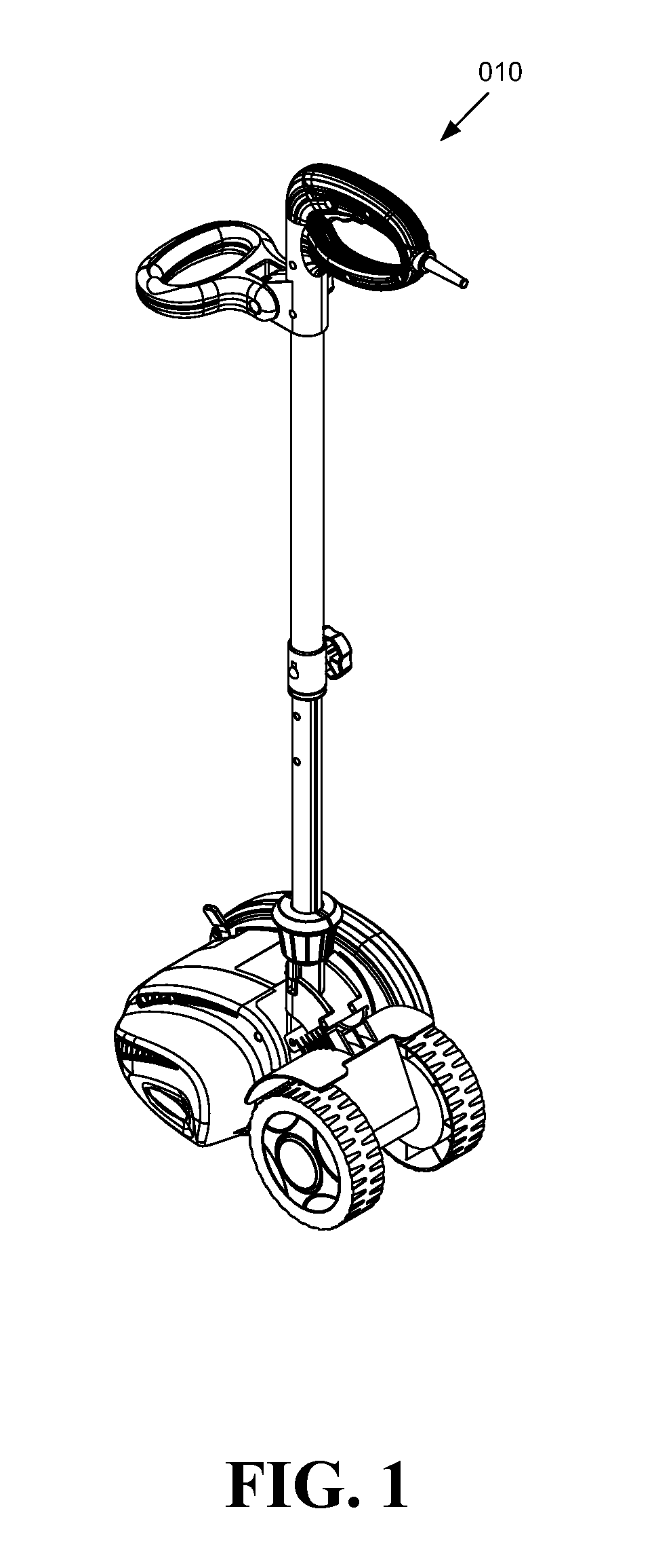
[0045]Referring now to FIGS. 1-23, a lawn edger 010 is shown comprising a pivotable shaft 100 for operational adjustability and compact storage of the lawn edger 010, the pivotable shaft 100 being generally cylindrical and located between a handle 200 and a motorized edging unit 300, the pivotable shaft 100 configured to pivot about the motorized edging unit 300 at a plurality of angles for varied use in operation and for compact storage of the lawn edger 010. The lawn edger 010 further comprises a removable blade guard 400, the removable blade guard 400 being entirely separable from the lawn edger 010 with a single push-b...


PUM


Abstract

A lawn edger operable to minimize storage space, have a completely removable blade guard, have a folding shaft, and have a convenient to operate edging depth adjustment, is disclosed. The removable blade guard incorporates a safety interlock that prevents operation of the motor and blade when the guard is removed. The lawn edger incorporates a pivoting, folding, shaft for compact storage, a removable blade guard for easy clean out and an easily adjustable front wheel for convenient edging depth adjustment.

Description

FIELD OF THE INVENTION[0001]The technology described herein relates generally to the field of power tools and more particularly to power edgers.BACKGROUND OF THE INVENTION[0002]Lawn edgers are well known in the art, however, existing devices have multiple problems. In general existing edgers take up too much storage space because of their long angled shaft and handle. In addition, the guard on conventional edgers becomes easily clogged with dirt and grass. Also some edgers use a complicated threaded clamp to hold the front wheel in various positions for adjusting edging depth. While selected edgers have provided a hinged door on the guard for clean out, this does not afford complete access to the blade area for cleaning. Additionally, while some edgers use a threaded knob adjustment it is not easy to manipulate and the response time could be faster. Finally, some edgers incorporate a liftable edging guide to prevent it from scraping on the ground that is less than desirable.[0003]Pa...

Claims


Application Information

Patent Timeline
Patent Type & Authority Applications(United States)
IPC IPC(8): A01D15/00
CPCA01G3/062A01D34/84
Inventor BRENEMAN, MATTHEW ROBERTTURNER, KIRK ALAN
Owner PRIZM INT
Learn More