
Method and apparatus for proximity activated RFID system

a technology of proximity activated rfid and proximity activated, which is applied in the field of security systems, can solve the problems of shortening the life of active tags, battery life, and the inability to turn on rfid readers all the time, and achieves the effect of low transmit power

Active Publication Date: 2009-10-01
JOHNSON CONTROLS TYCO IP HLDG LLP
View PDF8 Cites 30 Cited by
  • Summary
  • Abstract
  • Description
  • Claims
  • Application Information

AI Technical Summary

Benefits of technology

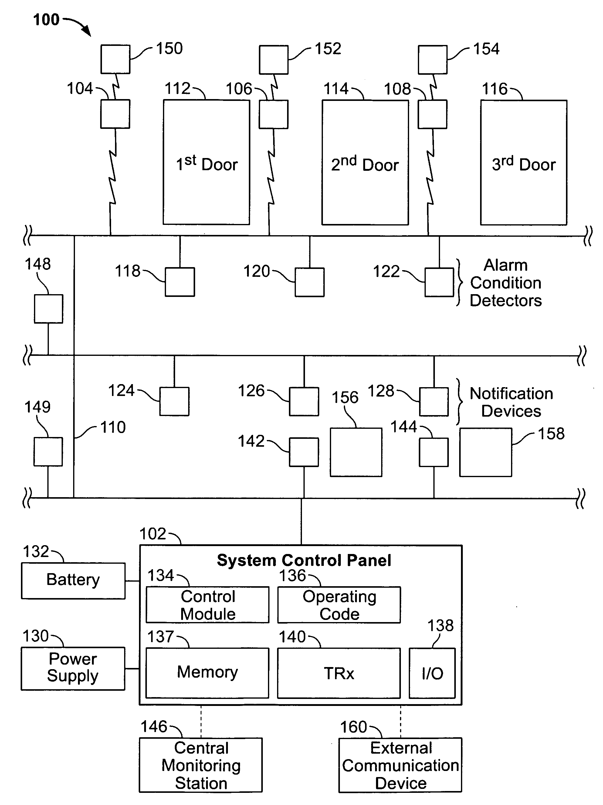
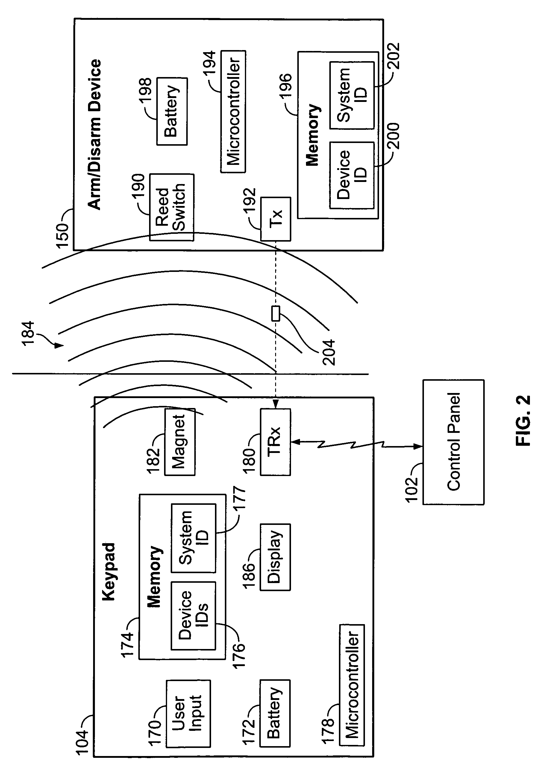
[0006]In one embodiment, a security system comprises a control panel configured to control devices in a security system, a keypad and an arm / disarm device. The keypad is in communication with the control panel and comprises a transceiver configured to communicate with the control panel and a magnet having a magnetic field extending within a predetermined proximity of the keypad. The arm / disarm device comprises a transmitter and a switch configured to activate the transmitter when the switch is in the magnetic field. The transmitter is further configured to transmit a low power signal when activated. The transceiver is further configured to receive the low power signal and transmit a message to the control panel. The control panel is further configured to change an Armed / Disarmed Mode of the system based on the message.
[0007]In another embodiment, a method for arming and disarming an alarm system comprises automatically activating an arm / disarm device when the arm / disarm device is within a predetermined proximity of a keypad. A device packet is transmitted with a low level of transmit power from the arm / disarm device to the keypad. The device packet is detected at the keypad. A message is transmitted based on the device packet from the keypad to a control panel, and an Armed / Disarmed Mode of the alarm system is changed based on the message.

Problems solved by technology

This shortens the life of the active tag.
Therefore, the RFID reader cannot be turned on all the time as the battery life would not be acceptable for a typical wireless application.

Method used


Image

  • Method and apparatus for proximity activated RFID system
  • Method and apparatus for proximity activated RFID system
  • Method and apparatus for proximity activated RFID system

Examples


Embodiment Construction

[0013]The foregoing summary, as well as the following detailed description of certain embodiments of the present invention, will be better understood when read in conjunction with the appended drawings. To the extent that the figures illustrate diagrams of the functional blocks of various embodiments, the functional blocks are not necessarily indicative of the division between hardware circuitry. Thus, for example, one or more of the functional blocks (e.g., processors or memories) may be implemented in a single piece of hardware (e.g., a general purpose signal processor or random access memory, hard disk, or the like). Similarly, the programs may be stand alone programs, may be incorporated as subroutines in an operating system, may be functions in an installed software package, and the like. It should be understood that the various embodiments are not limited to the arrangements and instrumentality shown in the drawings.

[0014]As used herein, an element or step recited in the singu...


PUM


Abstract

A security system comprises a control panel configured to control devices in a security system, a keypad and an arm / disarm device. The keypad is in communication with the control panel and comprises a transceiver configured to communicate with the control panel and a magnet having a magnetic field extending within a predetermined proximity of the keypad. The arm / disarm device comprises a transmitter and a switch configured to activate the transmitter when the switch is in the magnetic field. The transmitter is further configured to transmit a low power signal when activated. The transceiver is further configured to receive the low power signal and transmit a message to the control panel. The control panel is further configured to change an Armed / Disarmed Mode of the system based on the message.

Description

CROSS REFERENCE TO RELATED APPLICATIONS[0001]The application relates to and claims priority from provisional patent application Ser. No. 61 / 039,191, titled “PROXIMITY ACTIVATED RFID SYSTEM”, filed Mar. 25, 2008, the complete subject matter of which is expressly hereby incorporated herein in its entirety.BACKGROUND OF THE INVENTION[0002]This invention relates generally to security systems, and more particularly to using an arm / disarm device to arm and disarm the security system.[0003]Keypads are often located at secured doors and may be used to enter in codes to arm and disarm a security system. A keypad transceiver is used to communicate with the control panel of the security system. The keypad transceiver and associated electronics are in an ON or activated state to constantly scan for input from the surrounding, environment. Radio frequency identification (RFID) readers are often incorporated into the keypads for reading RFID tags or keytags that are carried by users of the system...

Claims


Application Information

Patent Timeline
Patent Type & Authority Applications(United States)
IPC IPC(8): G08B1/00G08B13/08G08B23/00
CPCG08B25/10G08B25/008
Inventor CHUL LEE, STEVEN SEUNGCHOY, JAKE
Owner JOHNSON CONTROLS TYCO IP HLDG LLP
Learn More