Two-grid ion energy analyzer and methods of manufacturing and operating

Active Publication Date: 2009-10-01
TOKYO ELECTRON LTD
View PDF16 Cites 33 Cited by
  • Summary
  • Abstract
  • Description
  • Claims
  • Application Information

AI Technical Summary

Benefits of technology

[0014]According to yet another embodiment, a method of measuring IED of plasma at one or more locations in a plasma processing system is described, comprising: placing one or more ion energy analyzers at the one or more locations on a substrate holder in a plasma processing system; and measuring an IED at each of the one or more locations by performing the following: exposing an entrance grid to the plasma at a DC self-bias potential; biasing an electron rejection grid proximate

Problems solved by technology

Although the IED has been measured extensively in plasma processes for decades using a variety of ion energy analyzers, most conventional analyzers suffer from a multitude of problems including, but not limited to: (1) Conventional analyzers perturb the processing plasma to an extent that the measurement is no longer characteristic of the conditions prevailing when processing a substrate; (2) Conventional analyzers fail to operate at large electric potentials; and (3) Conventional analyzers exhibit substantive noise arising from secondary electron emission within the analyzer.

Method used


Image

  • Two-grid ion energy analyzer and methods of manufacturing and operating
  • Two-grid ion energy analyzer and methods of manufacturing and operating
  • Two-grid ion energy analyzer and methods of manufacturing and operating

Examples


Embodiment Construction

[0026]In the following description, to facilitate a thorough understanding of the invention and for purposes of explanation and not limitation, specific details are set forth, such as a particular geometry of the plasma processing system and various descriptions of the system components. However, it should be understood that the invention may be practiced with other embodiments that depart from these specific details.

[0027]Nonetheless, it should be appreciated that, contained within the description are features which, notwithstanding the inventive nature of the general concepts being explained, are also of an inventive nature.

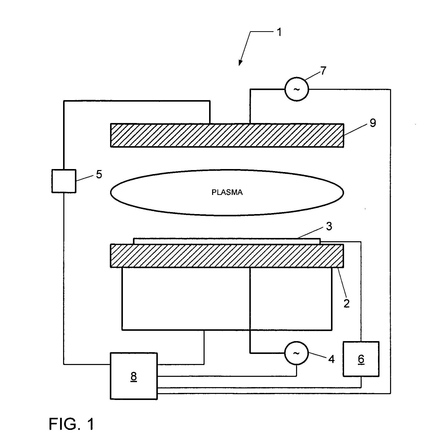
[0028]Referring now to the drawings, wherein like reference numerals designate identical or corresponding parts throughout the several views, FIG. 1 depicts a simplified schematic of a plasma processing system 1 according to an embodiment. The plasma processing system 1 comprises a first electrode 2 and a second electrode 9 disposed opposite each other within a...


PUM


Abstract

An ion energy analyzer is described for use in diagnosing the ion energy distribution (IED) of ions incident on a radio frequency (RF) biased substrate immersed in plasma. The ion energy analyzer comprises an entrance grid exposed to the plasma, an electron rejection grid disposed proximate to the entrance grid, and an ion current collector disposed proximate to the electron rejection grid. The ion current collector is coupled to an ion selection voltage source configured to positively bias the ion current collector by an ion selection voltage, and the electron rejection grid is coupled to an electron rejection voltage source configured to negatively bias the electron rejection grid by an electron rejection voltage. Furthermore, an ion current meter is coupled to the ion current collector to measure the ion current.

Description

CROSS-REFERENCE TO RELATED APPLICATIONS[0001]This application is related to co-pending U.S. patent application Ser. No. ______, entitled “ION ENERGY ANALYZER AND METHODS OF MANUFACTURING AND OPERATING”, Docket No. TEA-040, filed on even date herewith. The entire content of this application is herein incorporated by reference in its entirety.BACKGROUND OF THE INVENTION[0002]1. Field of the Invention[0003]The invention relates to an ion energy analyzer and a method for making and using the ion energy analyzer and, more particularly, to an ion energy analyzer for measuring ion energy distribution (IED) in a plasma processing system.[0004]2. Description of Related Art[0005]Plasma, or more generally an electrical discharge, has found extensive use in a variety of industrial applications, including material processing. For example, during semiconductor processing, plasma is often utilized to assist etch processes by facilitating the anisotropic removal of material along fine lines or with...

Claims


Application Information

Patent Timeline
IPC IPC(8): H01J37/04
CPCH01J37/05H01J37/32422H01J2237/053H01J49/443H01J37/32935
Inventor CHEN, LEEXU, LINBRAVENEC, RONALD VICTOR
Owner TOKYO ELECTRON LTD
Why Eureka
Try Eureka