
Hammer assembly for grand piano

a hammer and grand piano technology, applied in the field of key-operated percussion devices, can solve the problems of reducing the energy of key depression, wasting system energy or energy loss, and affecting the responsiveness of the piano action, so as to increase the efficiency of manufacture and maintenance, increase the efficiency of manufacturing and maintenance, and the effect of rigidity

Active Publication Date: 2009-09-24
WESSELL NICKEL & GROSS
View PDF1 Cites 0 Cited by
  • Summary
  • Abstract
  • Description
  • Claims
  • Application Information

AI Technical Summary

Benefits of technology

[0018]It is an object of this invention to provide a new hammer assembly for a piano that requires less initial energy from the pianist's fingers in order to deliver the same sound of that generated by currently available hammer assemblies. This can be accomplished by the elimination or substantial reduction of hammer assembly deflection, without increasing the weight of the hammer assembly. Thus, it is an object of this invention to yield an improved hammer assembly with substantially increased stiffness or rigidity without additional mass, thereby effectively providing a more responsive keyboard that requires less effort to play.
[0020]Additionally, it is an object of this invention to yield a hammer assembly with the collateral benefits of increased efficiency of manufacture and maintenance over those of their corresponding wood counterparts. Thus, it is an object of this invention to yield a more rigid hammer assembly without additional mass with the additional benefits of increased efficiency of manufacture and maintenance.

Problems solved by technology

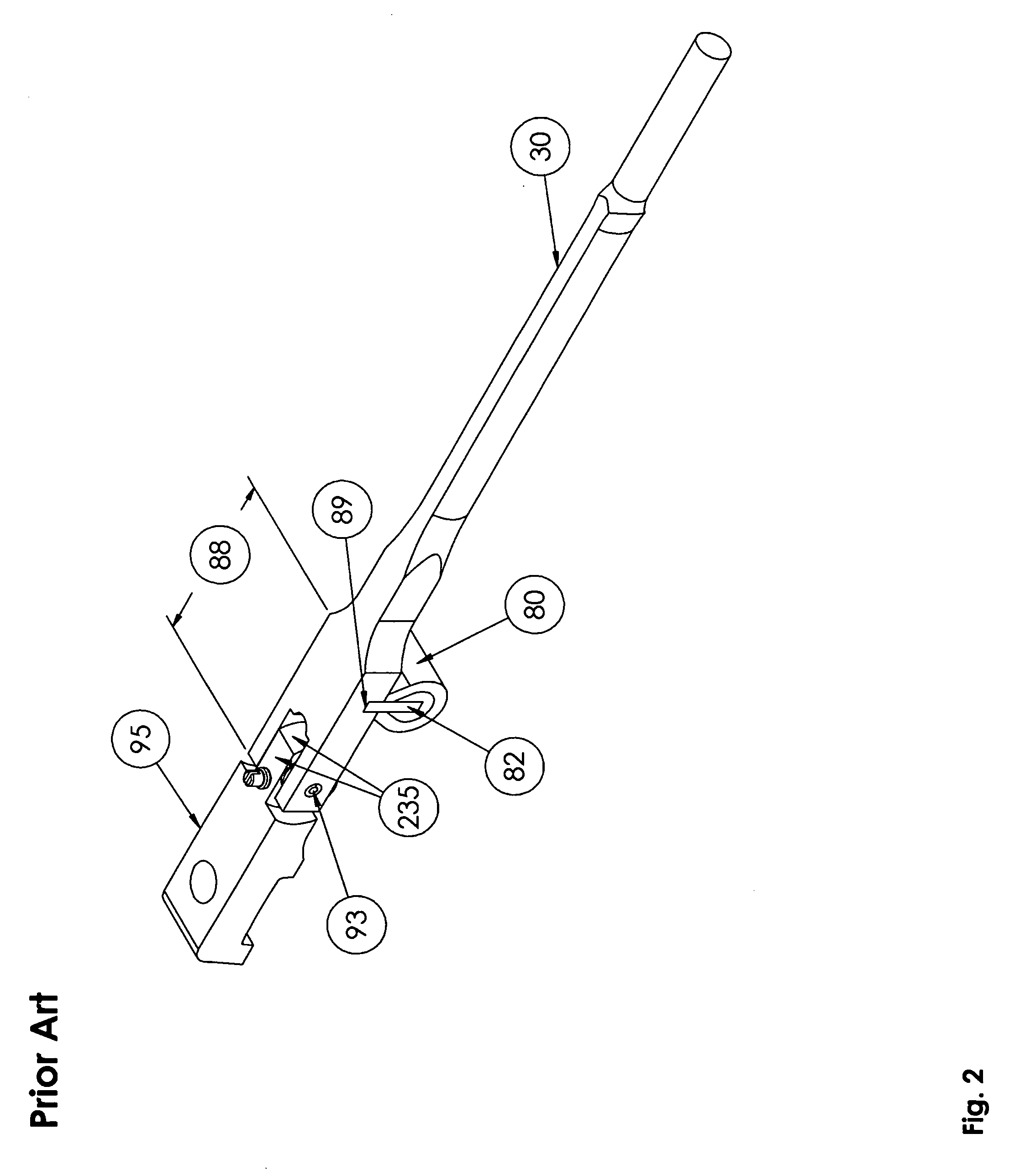
Since the energy absorbed by a bending of hammer shank 30 does not directly translate into the production of music, it is wasted energy or energy loss of the system.
Additionally, the weight of the hammer assembly affects the responsiveness of the piano action.
Likewise, a decrease in shank weight results in an exponential decrease in key depression energy.
Also, as a result of being wider, the forked end 88 is heavier, which also greatly reduces efficiency of this motion.
Relative to more modern materials, such as composites or plastics, wood is an inefficient raw material from which to manufacture piano action components.
The hole-drilling process is a laborious and costly process as compared to the production of molded piano action pieces with holes accurately formed therein during the initial molding process.
Also, the production of any finished wood piece necessarily involves relatively large quantities of wasted material in the form of saw dust, which is inefficient and wasteful.
This can cause binding in the action.
Additionally, after repeated occurrences, this causes compression of the wood leading to failure of the piano action component thus requiring excessive in field service.
For instance, wood flanges often crack due to expansion from a rise in moisture content, as the screw crushes the wood in the flange where it is fastened to the rail.
Moreover, wood has different strengths in different directions, complicating manufacturing processes, also resulting in reduced manufacturing efficiencies.
Additionally, wood has inferior rigidity and strength as compared to modern composites and plastics.
Finally, the lifespan of wood piano action components is limited as compared to that of other materials such as composites or plastics because wood over time deteriorates becoming weak and unserviceable.

Method used


Image

  • Hammer assembly for grand piano
  • Hammer assembly for grand piano
  • Hammer assembly for grand piano

Examples


Embodiment Construction

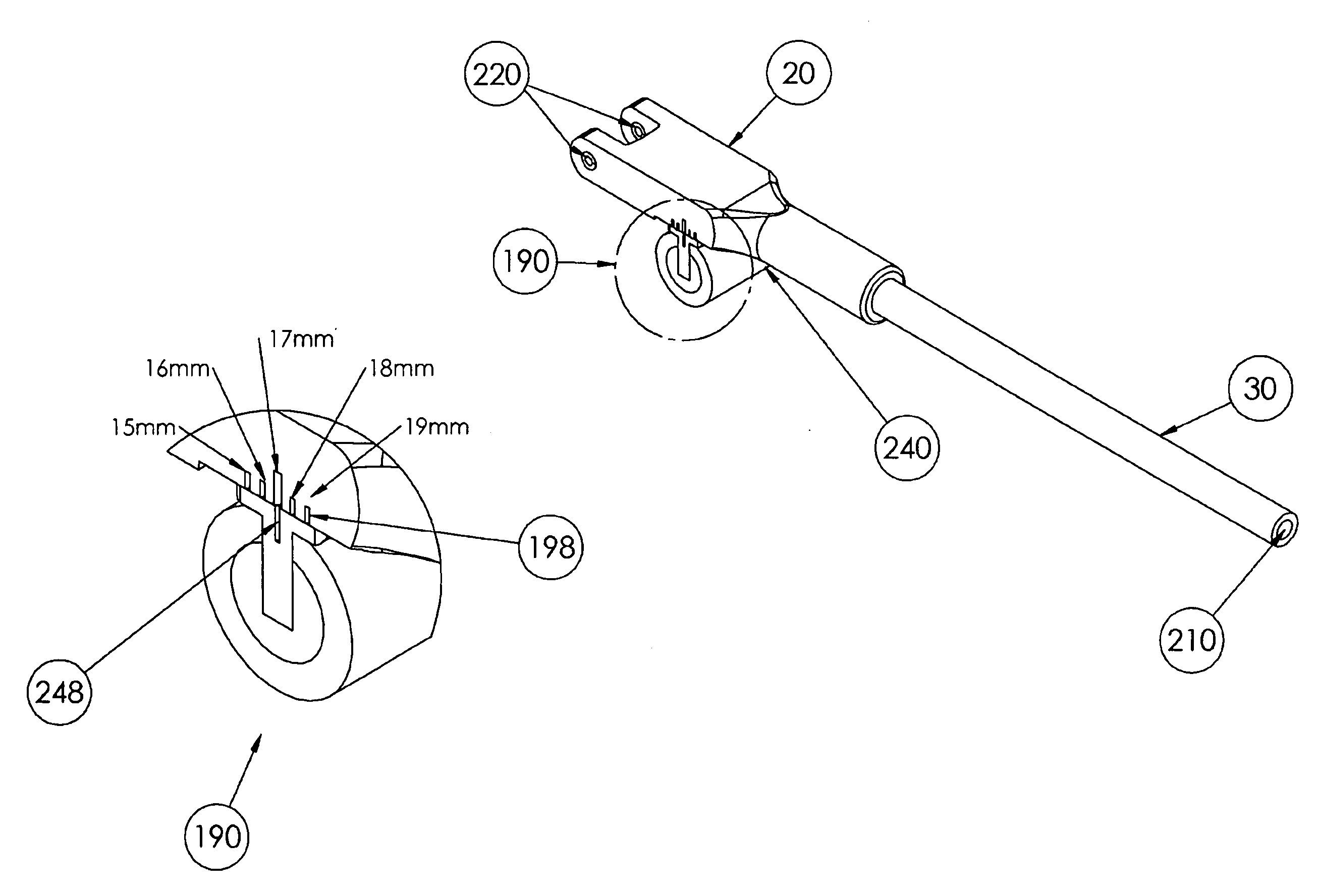
[0034]A hammer assembly of this invention comprises: a hammer 40; a hammer shank 30; a tubular lever interface 20; and a moveable knuckle 240. This invention includes novel hammer shanks 30, novel tubular lever interfaces 20, and novel moveable knuckles 240, where an assembly of such can be attached to prior art hammers 40 which are typically made of hornbeam wood and felt. The hammer assemblies of this invention can be installed into any grand piano of any brand.

[0035]All hammer shanks 30 of this invention are essentially cylindrically shaped made from composite or plastic material with an overall outer diameter range of 1-8 mm. Such hammer shanks 30 can be manufactured with less weight and more rigidity than their wood counterparts. This is particularly so when the hammer shank 30 is made of hollow form because hollow parts naturally weigh less than non-hollow parts. Thus, best mode hammer shank 30 of this invention is hollow in the center as depicted at 210. The hollow cross sect...


PUM


Abstract

A hammer assembly for a grand piano comprising: a hammer, a hammer shank, a tubular lever interface, and a moveable knuckle. A grand piano tubular lever interface comprises: a deep socket; a set of two hinge pin attachment holes; a void area; and a moveable knuckle visual location system. A moveable knuckle comprises: a spline; a resilient core; a synthetic buckskin wear surface, and a moveable knuckle visual location system. Novel hammer assembly allows for a direct lever relationship between hammer shank and knuckle without requirement of a forked end hammer shank with knuckle slot. Best mode spline comprises: an upright rectangular portion and a wide base portion, wherein wide base portion includes an intricate shape. Intricate shape comprises: at least one recess area and at least one protrusion area. The inverse of intricate shape is included on the bottom of the tubular lever interface. Moveable knuckle visual location system further comprises at least one pointer located on the moveable knuckle which fits snuggly into one of several notches on the tubular lever interface. Moveable knuckle can be visually located onto tubular lever interface at any one of multiple distinct locations along a range that runs parallel to the length of the hammer shank and the length of tubular lever interface. The moveable knuckle visual location system allows for custom configuration of a specifically dimensioned hammer assembly with custom “tubular lever interface center-to center” dimension to refurbish any brand of grand piano from one stock-set of hammer assembly components.

Description

CROSS-REFERENCE TO RELATED APPLICATIONS[0001]The instant application is a continuation-in-part of U.S. application Ser. No. 12 / 013,330 entitled “Hammer Shank and Shank Butt for Piano”, filed on Jan. 11, 2008. Claim 1 pertains to matter filed with the parent application. All additional claims claim the benefit of the instant application.BACKGROUND OF THE INVENTION[0002](1) Field of the Invention[0003]This invention relates to key operated percussion devices such as pianos and, more specifically, to the hammer assemblies of such devices. A hammer assembly according to this invention comprises: a hammer 40; a hammer shank 30; a tubular lever interface 20; and a moveable knuckle 240.[0004](2) Description of Prior Art[0005]A piano produces sound as a result of a complicated mechanical chain reaction which starts with the pianist depressing a piano key which in turn actuates a piano action 15 associated with a key 10 which in turn rotates a hammer assembly associated with the piano action...

Claims


Application Information

Patent Timeline
Patent Type & Authority Applications(United States)
IPC IPC(8): G10C3/18
CPCG10C3/18
Inventor CLARK, BRUCE E.BURKE, KEVINBURGETT, KIRK
Owner WESSELL NICKEL & GROSS
Learn More