
Table saws

a table saw and table saw technology, applied in the field of table saws, can solve problems such as difficulty in performing precise cutting operations, and achieve the effects of improving operability and versatility of positioning fences, and improving the versatility of table saws

Inactive Publication Date: 2009-09-24
MAKITA CORP
View PDF25 Cites 11 Cited by
  • Summary
  • Abstract
  • Description
  • Claims
  • Application Information

AI Technical Summary

Benefits of technology

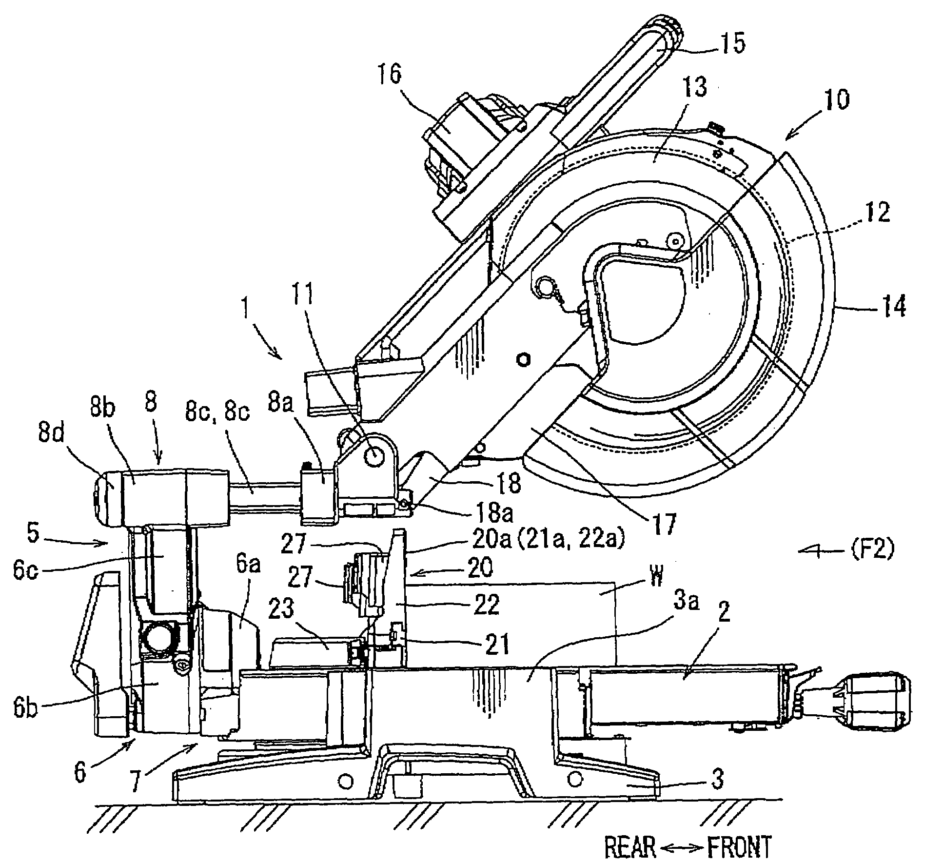
[0011]One aspect according to the present invention includes a table saw with a positioning fence. The positioning fence has a positioning surface for a workpiece that is formed with a first slide fence and a second slide fence that are vertically aligned with each other. The positioning surface can be slidably moved by moving the first slide fence and / or the second slide fence. In this way, the first lower slide fence can also be moved between a position close to the rotary blade and a position away from the rotary blade. Therefore, a clearance defined between the rotary blade and the fence can be determined to be minimum without being interfered by the rotary blade when the inclined cutting operation or the angle cutting operation is normally performed. Consequently, even when the cutting operation is performed with small width, the cutting operation can be performed with a workpiece securely fixed in a position while a workpiece is abutted to the first or second fences. Therefore, a positioning function of the positioning fence can be reliably exercised.
[0014]In another aspect, the table saw includes a slide support portion of the first slide fence relative to a frame and a slide support portion of the second slide fence relative to the first slide fence. Even though a rattling (a clearance) is generated in a direction perpendicular to the sliding direction due to an inaccuracy by processing or mounting these slide support portions, rattling can be controlled by adjusting a penetration depth of a screw provided for a clearance restricting member. Therefore, it is possible to achieve an accurate and quick positioning.
[0016]In another aspect, the operability and the versatility of the table saw can be improved, because the positioning fence can be used in a mode in accordance with various factors, for example, a size and / or a configuration of a workpiece. In addition, even a large workpiece can be securely positioned, because a positioning surface to be pressed against a workpiece can be maintained to be large while the cutting unit is avoided to interfere with the rotary blade.
[0017]In another aspect, more detailed mode selection is possible in accordance with various factors, for example, a size and / or a configuration of a workpiece while the cutting unit is avoided to interfere with the rotary blade. Accordingly, the operability and the versatility of the positioning fence can be improved.

Problems solved by technology

Therefore, it may be difficult to perform an exact cutting operation because a positioning accuracy for a narrow part of the workpiece is not ensured.

Method used


Image

  • Table saws
  • Table saws
  • Table saws

Examples


second embodiment

[0060]As shown in FIG. 9, the positioning fence 30 includes a pair of first slide fences 31 and a pair of second slide fences 32 arranged on the left and right side. Front surfaces of the first slide fences 31 define first positioning surfaces 31a and are allocated to lower positioning surfaces. Front surfaces of the second slide fences 32 define second positioning surfaces 32a and are allocated to the upper positioning surfaces. The first positioning surfaces 31a and the second positioning surfaces 32a are aligned to be flush with each other and form a single large positioning surface. The first slide fences 31 are slidably supported extending over left and right lateral frame portions 33a of a frame 33. The left and right lateral frame portions 33a are connected by means of a semicircular arch connecting portion 33b. The left and right lateral frame portions 33a are secured to an upper surface of a base portion 3a of a base 3, respectively.

first embodiment

[0061]Slide groove portions 33c are provided on the upper surfaces of the left and right lateral frame portions 33a extending along the longitudinal directions. Lower slide rail portions 31b of the first slide fences 31 are slidably supported within the slide groove portions 33c. Upper slide rail portions 31c are provided on the upper surfaces of the left and right slide fences 31, respectively. The upper slide rail portions 31c are slidably supported within slide grooves 32b defined on the lower surfaces of the second slide fences 32. In this way, similar to the first embodiment, the first and second slide fences 31 and 32 are supported to be able to slide relatively independent in a radial direction of the table 2.

[0062]Clearance restricting members 34 that can be adjusted by screws, are provided to the left and right lateral frame portion 33a, respectively. As shown in FIG. 9, a support hole 33d is formed at the rear surface of the lateral frame portion 32a. The support hole 33d ...


PUM

PropertyMeasurementUnit
Depthaaaaaaaaaa
Levelaaaaaaaaaa

Abstract

A table saw includes a table capable of supporting a workpiece, a cutting unit and a positioning fence. The positioning fence has a positioning surface for supporting the workpiece. The positioning surface is divided into an upper positioning surface and a lower positioning surface that are positioned above the table. First slide fences allocated to the lower positioning surface and second slide fences allocated to the upper positioning surface are slidably supported in a table surface direction relatively independent from each other. The positioning surfaces of the first and second slide fences constitute an entire region of the positioning surface. In this way, the entire region of the positioning surface is made to be slidable in accordance with various operation modes.

Description

[0001]This application claims priority to Japanese patent application serial numbers 2008-73914 and 2008-307292, the contents of which are incorporated herein by reference.BACKGROUND OF THE INVENTION[0002]1. Field of the Invention[0003]The present invention relates to table saws for cutting a workpiece by means of a cutting unit having, for example, a circular grinder or a rotary blade such as a saw blade. In particular, present invention relates to table saws that have a positioning fence for positioning and fixing a workpiece on a table and cut or perform other working operations on a workpiece by moving the cutting unit in a downward direction.[0004]2. Description of the Related Art[0005]Table saws have included a table for placing and fixing a workpiece thereon, and a cutting unit supported operably movable relative to the table in a vertical direction. The cutting unit has an electric motor as a power source and a circular rotary blade driven by the electric motor. When an oper...

Claims


Application Information

Patent Timeline
IPC IPC(8): B23D19/00
CPCB23D47/04B27B27/08Y10T83/7788Y10T83/7722Y10T83/7705Y10T83/7693Y10T83/7613
Inventor KANI, TOSHIYUKIMIURA, MASAHIKOKOJIMA, SHINYAABE, KENJI
Owner MAKITA CORP
Learn More