
Quick-change device

a technology of quick-change device and hydraulic coupling, which is applied in the direction of lifting device, bearing, mechanical machine/dredger, etc., can solve the problems of high spreading force, large environmental damage, and leakage of hydraulic couplings to fail

Inactive Publication Date: 2009-09-24
LEHNHOFF HARTSTAHL
View PDF6 Cites 8 Cited by
  • Summary
  • Abstract
  • Description
  • Claims
  • Application Information

AI Technical Summary

Benefits of technology

[0013]According to one embodiment of the invention, a drive unit is able to move at least parts of the mechanical retaining means from a change position to the operating position and / or from the operating position to the change position. This is advantageous especially from the standpoint of the ease of operation of the quick-change device.
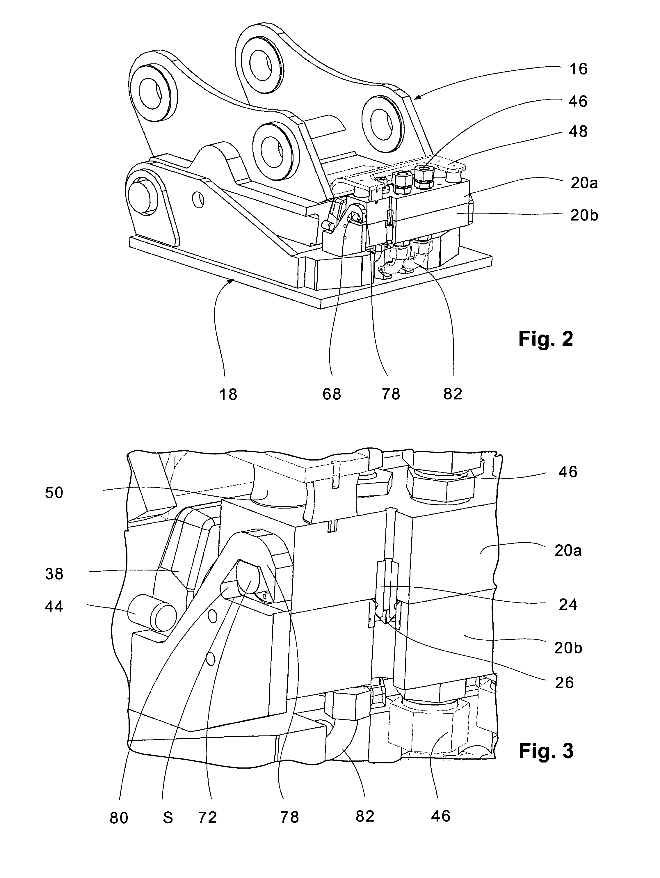
[0031]The invention is based on the realization that, by designing the mechanical means for securing the hydraulic coupling in such a way that their movements are linear, a compact but efficient device is made possible.

Problems solved by technology

As a result of the spreading forces which occur during operation, the hydraulic couplings can leak and ultimately fail.
This can also lead to considerable environmental damage.
The problem with this design, however, is that, in certain types of applications, the hydraulic pressures are very high, and these therefore cause very high spreading forces.
Considerable effort is therefore required to counteract these spreading forces by means of a hydraulically produced pressure.
It has been found, however, that, when the spreading forces are very high, either the mechanical means undergo fatigue and break or the material creeps, which causes the mechanical means to jam.
As a result, the hydraulic coupling can no longer be disconnected, and, depending on the embodiment, the quick changer is also blocked.

Method used


Image

  • Quick-change device
  • Quick-change device
  • Quick-change device

Examples


Embodiment Construction

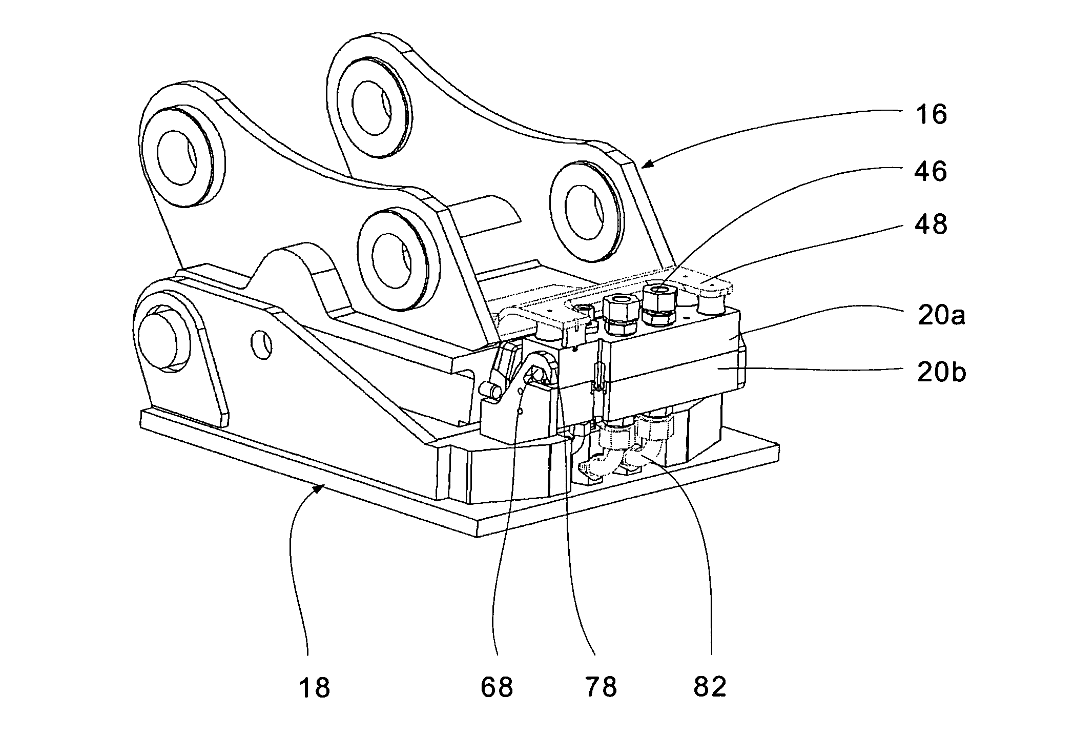
[0043]FIG. 1 shows the arm 10 of a working machine, namely, an earth-moving machine, such as an excavator, in perspective. At the end of the arm 10 there is a quick-change device 12, which is connected in turn to a conventional sorting bucket 14.

[0044]The quick-change device 12 consists of a quick changer 16 connected to the arm 10 and an adapter 18. The adapter 18 is permanently mounted on the bucket 14. Through the use of the quick-change device 12, the arm 10 can be connected to various tools such as the illustrated sorting bucket 14 by way of the adapter. Instead of the sorting bucket 14 mentioned above, it is also possible to use other tools, especially those which are hydraulically operated, such as hydraulic hammers, hydraulic shears, etc.

[0045]These tools are driven by a hydraulic drive, which is powered by the working machine. For this purpose, the quick-change device 12 has a hydraulic coupling 20. The tool, in this case the bucket 14, is connected to the hydraulic system ...


PUM


Abstract

Quick-change device (12) comprising a quick coupler (16) fastened on the driven-machine side, an adapter (16) which can be locked with the quick coupler (16) and is connected to a tool (14), and a hydraulic coupling (20) for producing a hydraulic connection between the hydraulic system on the driven machine and the hydraulics of the tool (14), wherein the hydraulic coupling (20) includes a first coupling part (20a) and a second coupling part (20b) and the two coupling parts (20a, 20b) are held relative to one another in an operating position, wherein the first coupling part (20a) and the second coupling part (20b) interact with at least mechanical retaining means (68,78,80) which are formed separately from the locking means of the quick-change device (12). The invention is distinguished by the fact that the coupling parts (20a, 20b) are held frictionally in the operating position by the mechanical retaining means (67,78, 80).

Description

[0001]Applicant claims priority to German patent application DE 10 2006 023 420.0 filed May 17, 2006.FIELD OF THE INVENTION[0002]The present invention pertains to a quick-change device.BACKGROUND OF THE INVENTION[0003]Many different embodiments of this type of quick-change device have become known.[0004]A first embodiment of a quick-change device is known from, for example, EP 0 483 232 B1 and consists of a quick changer, comprising a pivoting and locking device, and an adapter. The quick changer is assigned to the arm of the excavator, and the opposing adapter, which is to be connected to the quick changer, is mounted on an exchangeable tool such as a sorting bucket.[0005]The pivoting and locking device described in the publication cited above locks the adapter and the quick changer together, but it also brings the hydraulic couplings for the hydraulic fluid together. To bring these hydraulic couplings together, they must be pivoted over a relatively long distance. As a result of t...

Claims


Application Information

Patent Timeline
Patent Type & Authority Applications(United States)
IPC IPC(8): F16D3/80E02F3/96F16D1/10F16C7/04
CPCE02F3/3654Y10T74/2142Y10T403/22E02F3/3663
Inventor MULLER, PETER
Owner LEHNHOFF HARTSTAHL
Learn More