
Surgical material applicator

a technology of material applicators and rods, applied in the field of surgical material applicators, can solve the problems of slipping about the rod, inconvenient use, time-consuming and unreliable,

Inactive Publication Date: 2009-09-17
SOLTZ MICHAEL ANDREW +2
View PDF20 Cites 7 Cited by
  • Summary
  • Abstract
  • Description
  • Claims
  • Application Information

AI Technical Summary

Problems solved by technology

Conventional methods, including a variety of mesh applicators, are inefficient, time consuming and unreliable.
The mesh is often difficult to attach to the rod and thus may slip about the rod.

Method used


Image

  • Surgical material applicator
  • Surgical material applicator
  • Surgical material applicator

Examples


Embodiment Construction

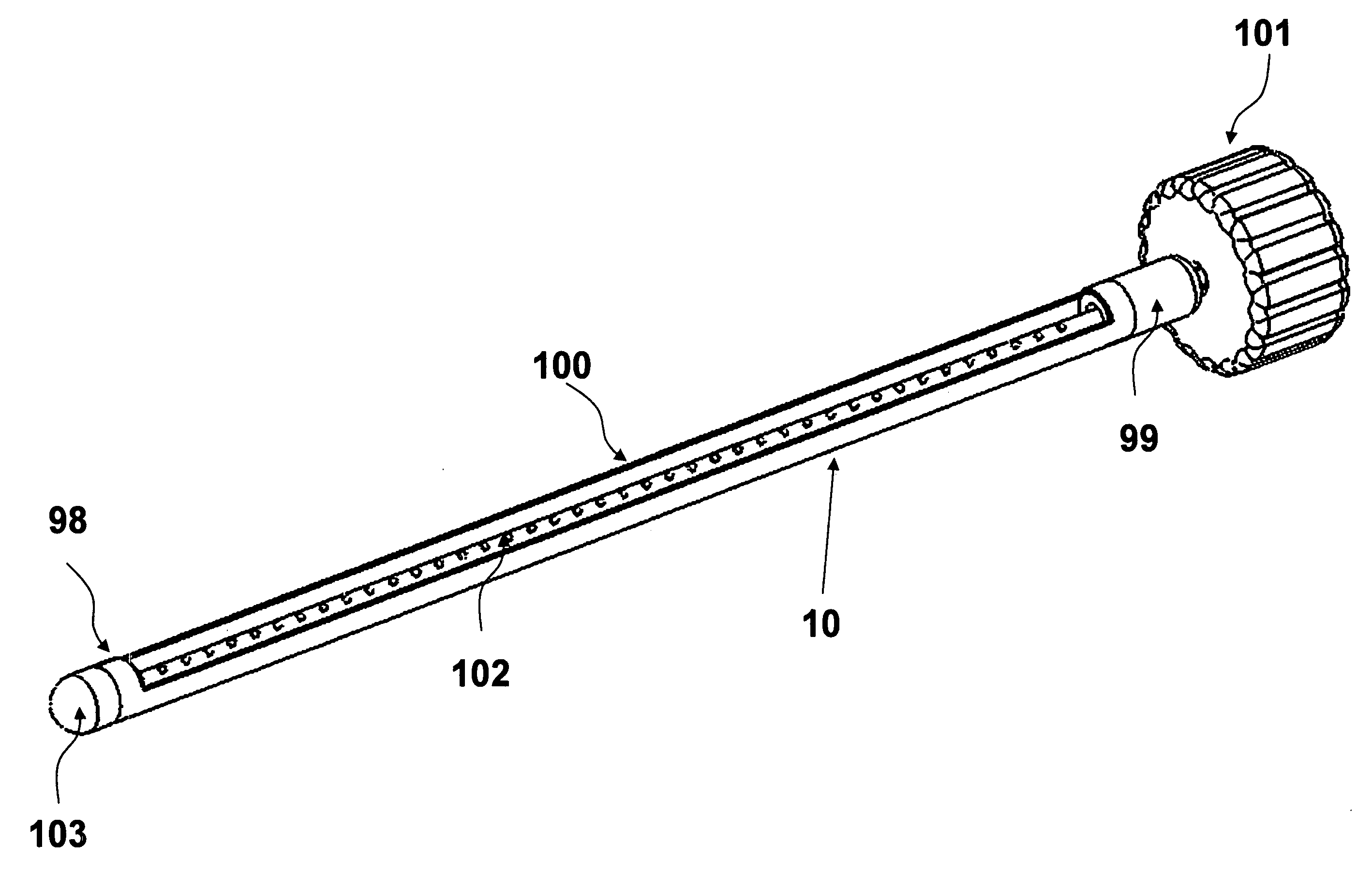
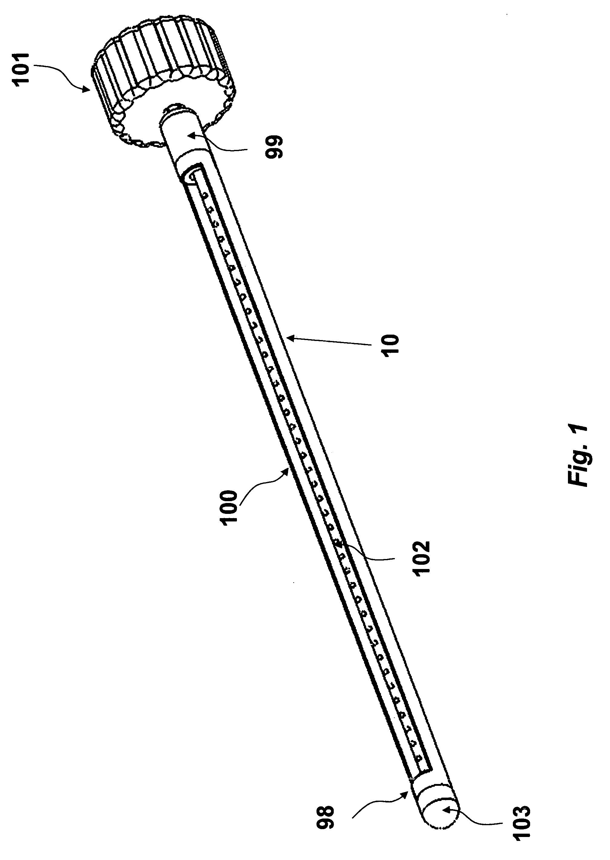
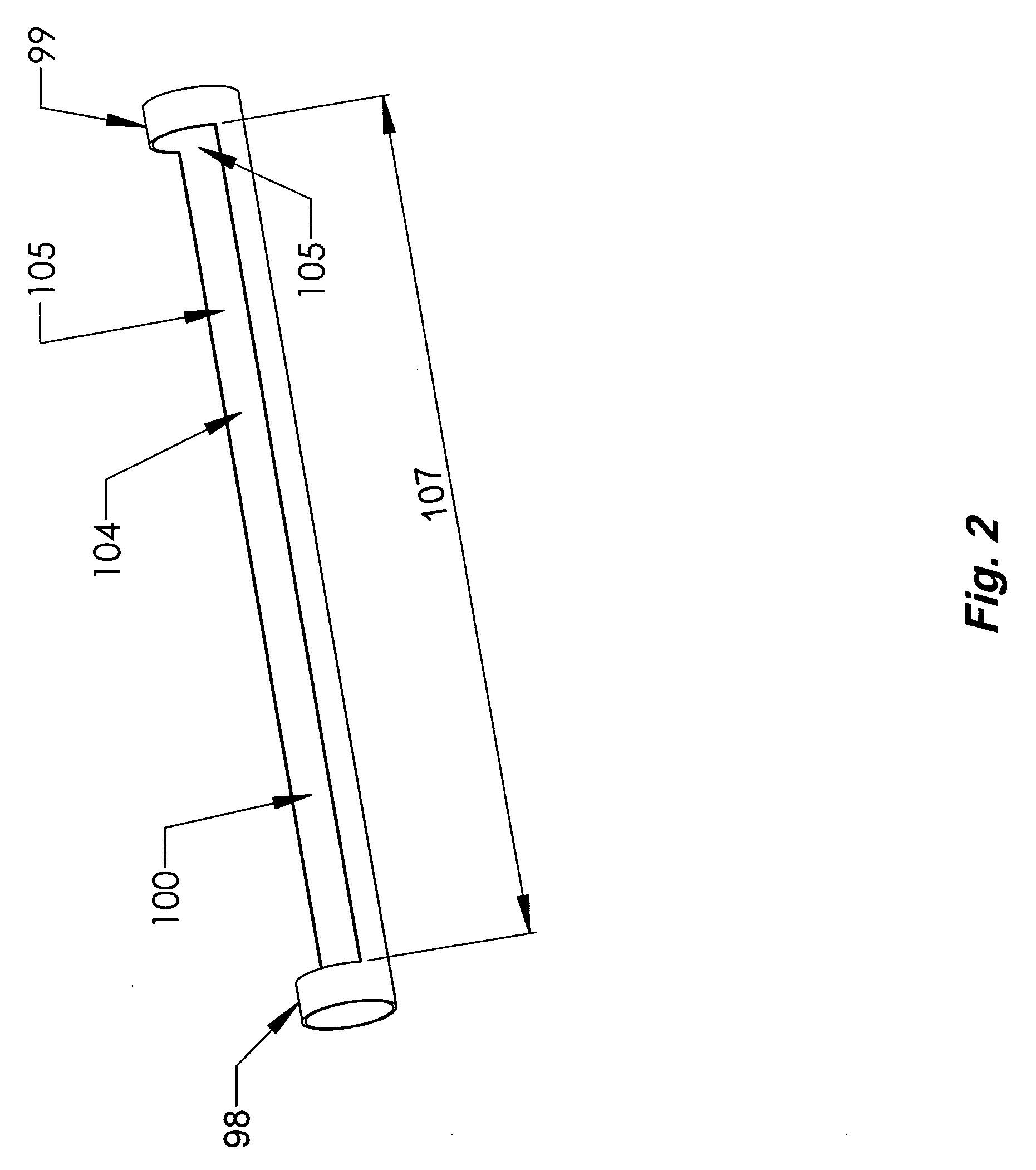
[0020]Consistent with an aspect of the present disclosure, surgical material is contained within the sheath while it is introduced into the abdominal cavity, thereby preventing a premature discharge of the mesh before it is properly positioned over the defect. As a result, material introduction is low risk, quick, inexpensive and reproducible. Specifically, the surgical material is prevented from folding over on itself and will provide the necessary control to achieve the desired registration and orientation of the surgical material within the abdominal cavity. Commonly used composite materials including relatively thin meshes that are structurally weak as well as thick, rigid materials can be reliably positioned so that the coated or adhesion barrier side of the material will typically be placed toward the bowel while the uncoated side will face the abdominal wall. In this manner, adhesion formation and viscus erosion can be prevented. Furthermore thick, large sheets of a surgical ...


PUM


Abstract

Consistent with an aspect of the present disclosure, a mesh or other surgical material is wrapped about one or more shafts, and inserted into a body cavity where it is unfurled and placed over a tissue site, such as a hernia. The mesh, for example, is secured to the shaft in order to prevent crimping or crumpling thereof during deployment over the tissue site.

Description

[0001]This application claims priority to U.S. Provisional Patent Application Ser. No. 61 / 066,071 filed on Feb. 15, 2008, which is incorporated by reference herein in its entirety.STATEMENT OF RIGHTS TO INVENTIONS MADE UNDER FEDERALLY SPONSORED RESEARCH[0002]This work was supported in part by the National Institute of Diabetes and Digestive and Kidney Diseases grant number 2R44 DK062571. The government has certain rights in the invention.BACKGROUND TO THE INVENTION[0003]In many surgical procedures, a surgical material is introduced into a body cavity and placed over a wound or tissue defect. For example, in a hernia repair procedure, a mesh is placed over a hernia in order to repair it. Many different meshes have been developed for this purpose. For example, meshes having different thicknesses and other structural properties are used for different size hernias. Moreover, meshes have been coated with materials to reduce inflammation of adjacent tissues and to minimize adhesions.[0004...

Claims


Application Information

Patent Timeline
Patent Type & Authority Applications(United States)
IPC IPC(8): A61B17/03
CPCA61B17/3468A61F2002/0072A61F2/0063
Inventor SOLTZ, MICHAEL ANDREWSOLTZ, ROBERTLANZAFAME, RAYMOND J.
Owner SOLTZ MICHAEL ANDREW
Learn More