
Method and apparatus for transmitting a pilot in multi-antenna system

a multi-antenna system and pilot technology, applied in the field of wireless communication, can solve the problems of unsecure snr gain and yield improvement, complicated channel environment of multi-antenna system, etc., and achieve the effect of improving channel estimation performan

Active Publication Date: 2009-09-17
LG ELECTRONICS INC
View PDF7 Cites 42 Cited by
  • Summary
  • Abstract
  • Description
  • Claims
  • Application Information

AI Technical Summary

Benefits of technology

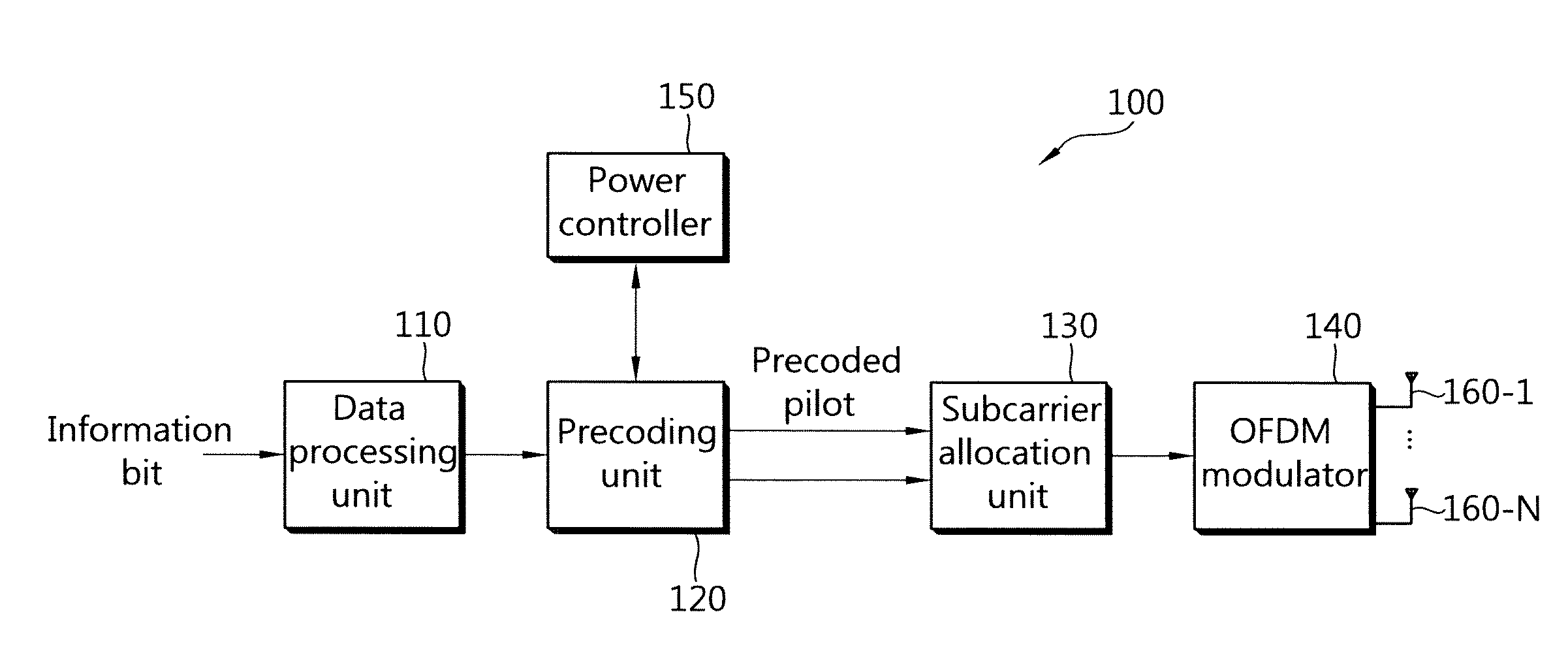
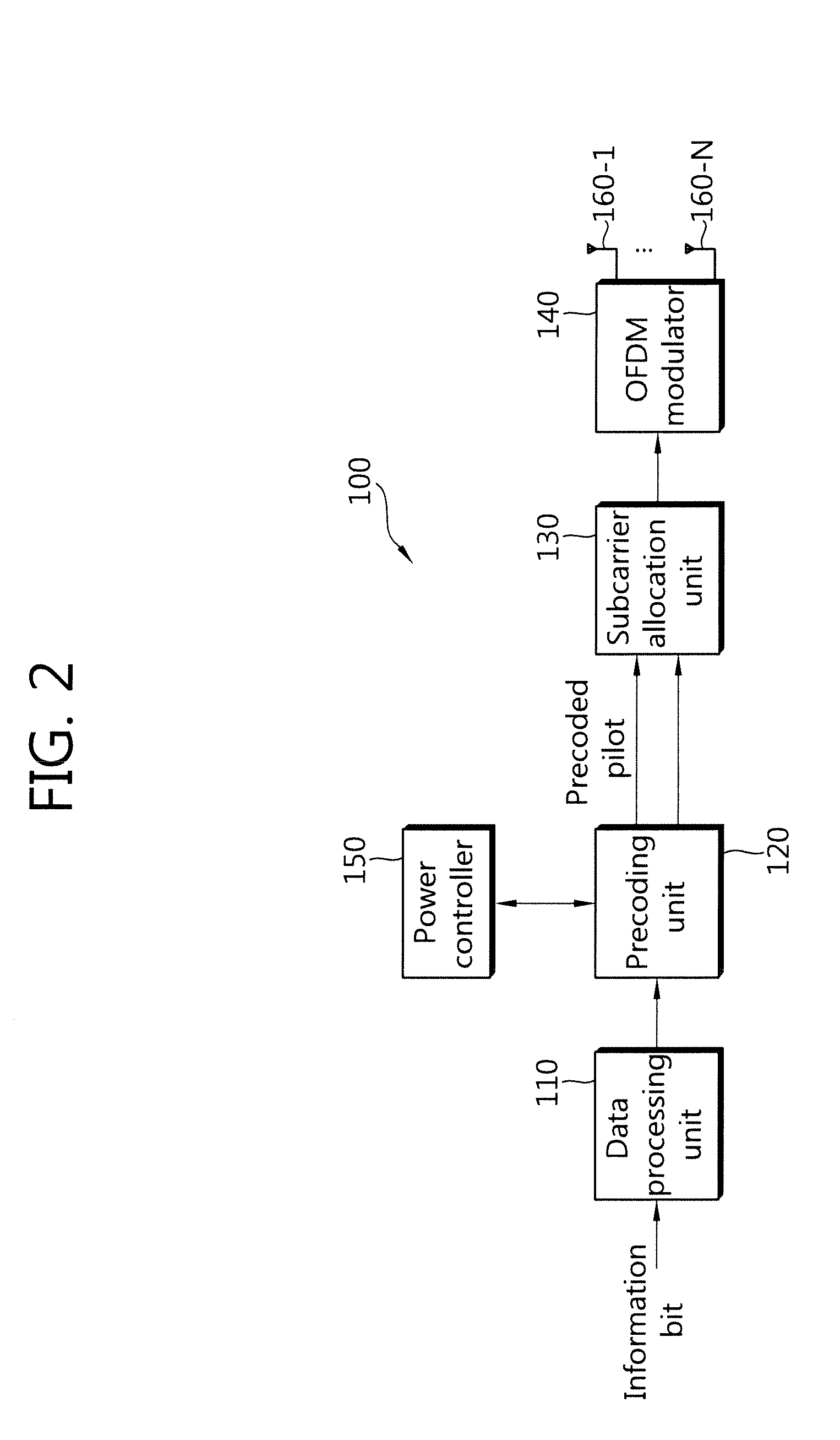
The present invention provides a method and apparatus for transmitting a pilot to improve channel estimation in a multi-antenna system. The method includes generating a preceding matrix including a preceding vector, applying the preceding vector to each of data streams, and transmitting the precoded pilot. The transmission power of the precoded pilot is determined specifically to each data stream. The apparatus includes a preceding unit preceding pilots, a power controller controlling transmission powers of the precoded pilots, a subcarrier allocation unit mapping the precoded pilots to subcarriers, an OFDM modulator performing inverse fast fourier transformation on the precoded pilots mapped to the subcarriers, and multiple antennas transmitting the OFDM symbols. The invention allows for individual and independent control of the transmission power of each pilot, improving channel estimation performance.

Problems solved by technology

However, a multi-antenna system has a very complicated channel environment and the SNR gain and yield improvement are not secured for all the complicated channels of the multi-antenna system because there is a limitation in achieving a SNR gain and yield improvement for data streams subjected to a very poor channel among data streams input to a preceding unit and respectively transmitted to a receiver through different channels.

Method used


Image

  • Method and apparatus for transmitting a pilot in multi-antenna system
  • Method and apparatus for transmitting a pilot in multi-antenna system
  • Method and apparatus for transmitting a pilot in multi-antenna system

Examples


Embodiment Construction

[0024]Hereinafter, an embodiment of the present invention will be described below with reference to the accompanying drawings.

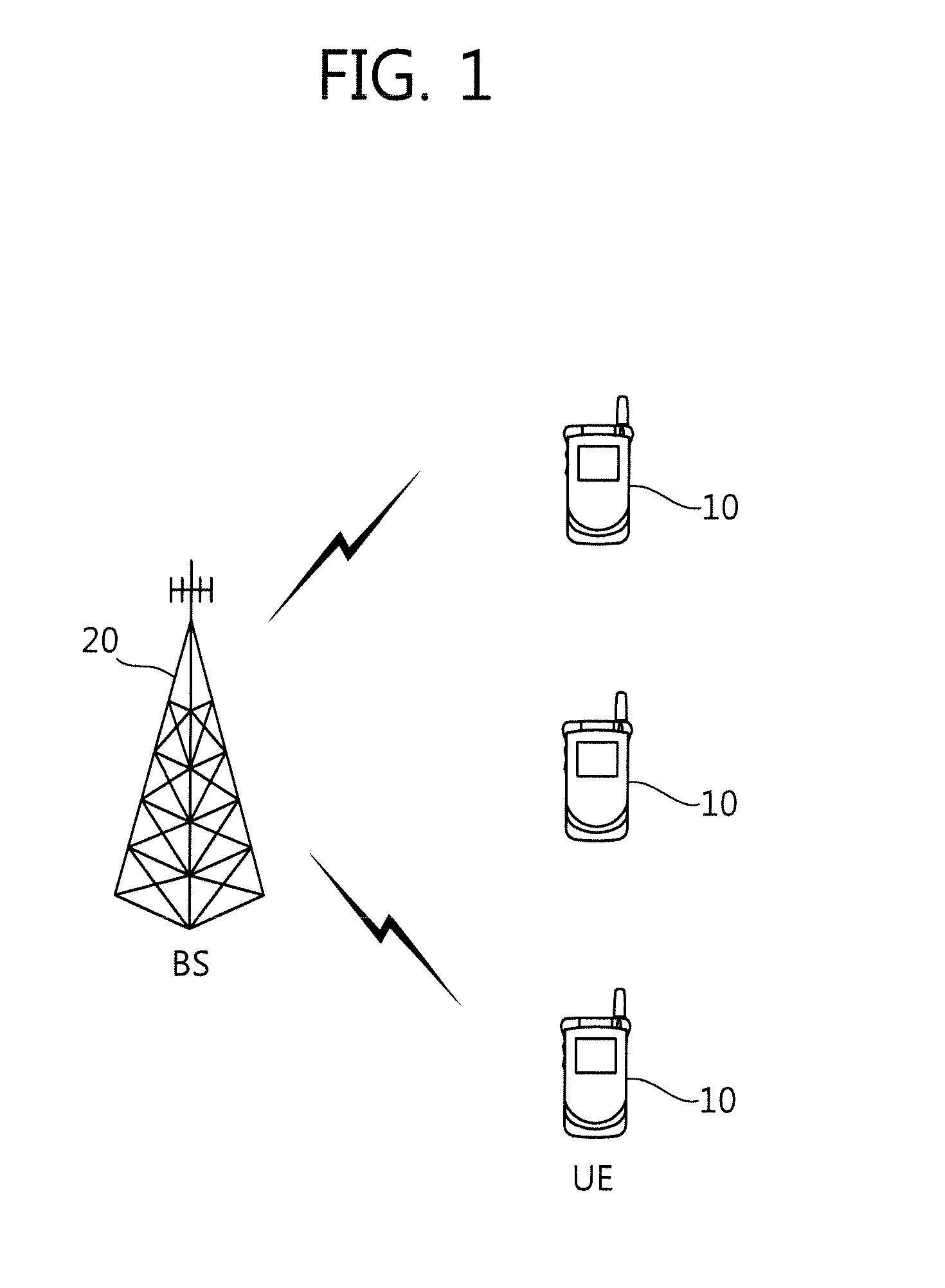
[0025]FIG. 1 illustrates a wireless communication system. The wireless communication system is widely distributed to provide a variety of communication services such as audio data and packet data.

[0026]Referring to FIG. 1, the wireless communication system includes user equipment (UE) 10 and a base station (BS) 20. The UE 10 can be fixed or movable and referred to as other terms such as a mobile station, a user terminal, a subscriber station, and a wireless device. The BS 20 is a fixed station communicating with the UE 10 and can be referred to as other terms such as a node-B, a base transceiver system, and an access point. A single BS can include at least one cell.

[0027]A downlink (DL) means transmission of data from the BS 20 to the UE 10 and an uplink (UL) means transmission of data from the UE 10 to the BS 20 in the following description. In the downlink,...


PUM


Abstract

A method of transmitting a pilot method in a multi-antenna system is provided. The method comprises generating a preceding matrix including a preceding vector, the preceding vector being applied to each of data streams to be transmitted, performing preceding procedure for a pilot by using the preceding matrix, and transmitting the precoded pilot, wherein transmission power of the precoded pilot is determined specifically to the each of the data streams. The transmission power of a precoded pilot can be controlled adaptively, individually and independently for each channel to improve channel estimation performance.

Description

CROSS-REFERENCE TO RELATED APPLICATIONS[0001]This application claims the benefit of priority of U.S. Provisional Application No. 61 / 035,744 filed on Mar. 12, 2008, and Korean Patent Application No. 10-2008-0100859 filed on Oct. 14, 2008, which are incorporated by reference in their entirety herein.BACKGROUND[0002]1. Field of the Invention[0003]The present invention relates to wireless communication, and more particularly, to a method and apparatus for transmitting a pilot in a multi-antenna system.[0004]2. Related Art[0005]With the popularization of information communication services and the advent of a variety of multimedia services and high-quality services, demands for communication services are rapidly increased. To satisfy these demands, various wireless communication techniques are studied in various fields.[0006]Next-generation wireless communication systems are required to transmit high-quality large-capacity multimedia data at a high speed by using limited frequency resourc...

Claims


Application Information

Patent Timeline
Patent Type & Authority Applications(United States)
IPC IPC(8): H04L27/28H04L27/00
CPCH04B7/0413H04L5/005H04L5/0051H04W52/325H04L25/03343H04L2025/03414H04L2025/03802H04L5/0053
Inventor KO, HYUN SOOCHUN, JIN-YOUNGLEE, MOON ILIHM, BIN CHULLEE, WOOK BONG
Owner LG ELECTRONICS INC
Learn More