Electric motor
a technology of electric motors and motors, applied in the direction of synchronous motors, windings, dynamo-electric components, etc., can solve the problems of poor response to coil current control and difficulty in obtaining higher efficiency, and achieve the effect of improving the electric characteristics of electric motors
- Summary
- Abstract
- Description
- Claims
- Application Information
AI Technical Summary
Benefits of technology
Problems solved by technology
Method used
Image
Examples
first embodiment
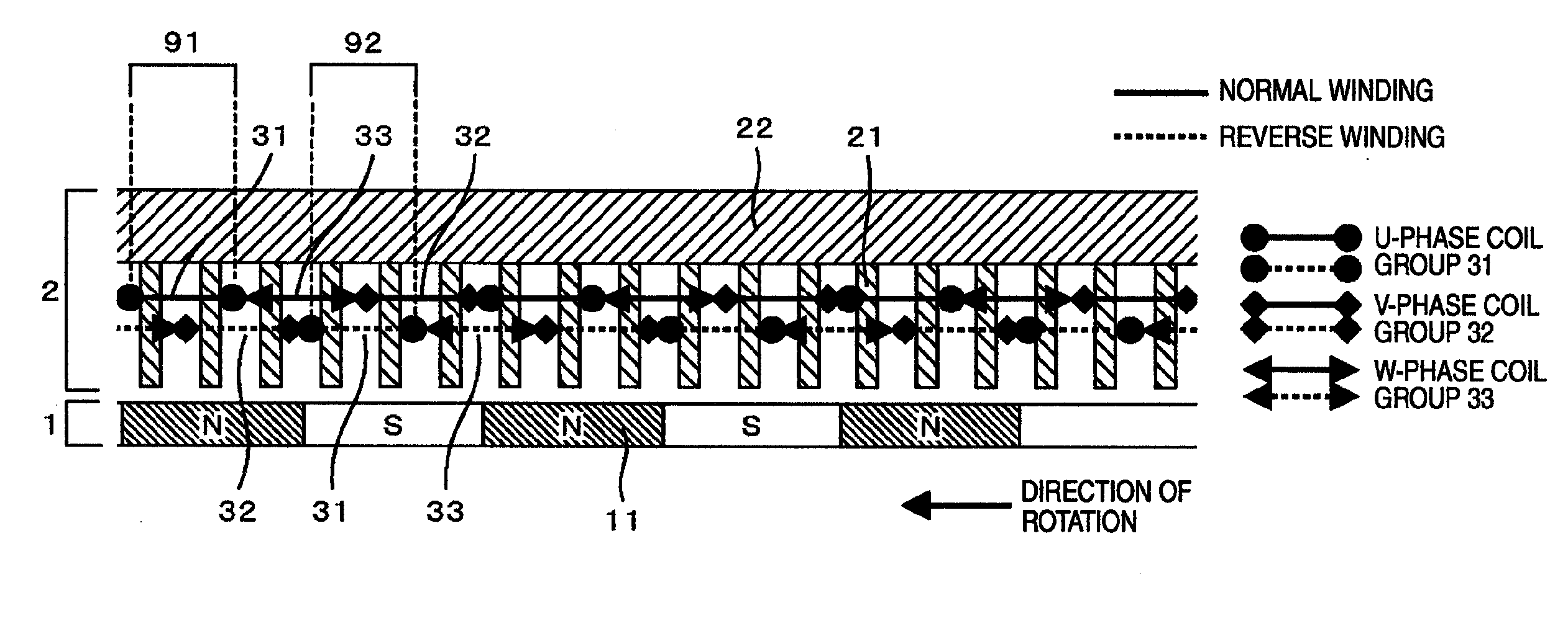
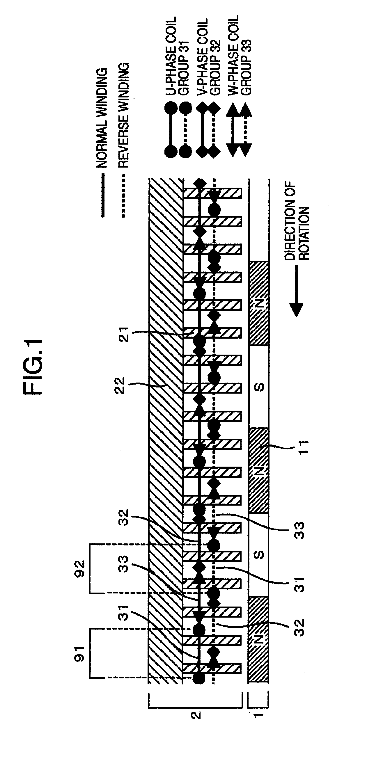
[0053]FIG. 1 schematically shows an electric motor, with its air gap portion developed linearly along the circumferential direction of the rotor. The electric motor comprises a rotor 1 and a stator 2 in principle. The rotor 1 has plural rotor magnetic poles 11, and the stator 2 has plural teeth 21 serving as stator magnetic poles. Coil units of U-phase coil group 31, V-phase coil group 32 and W-phase coil group 33 are wound around teeth 21 of the stator core. It should be noted here that the V-phase coil unit, i.e. an individual coil unit of the V-phase coil group, is the coil unit through which flows an alternating current having its phase lagging by 120 degrees (or leading by 240 degrees) from the phase of the current flowing through the U-phase coil unit, i.e. an individual coil unit of the U-phase coil group, and that the W-phase coil unit, i.e. an individual coil unit of the W-phase coil group, is the coil unit through which flows an alternating current having its phase lagging...
third embodiment
[0082]FIG. 10 schematically shows an electric motor, with its air gap portion developed linearly along the circumferential direction of the rotor. Except the items described below, this embodiment is the same as the embodiments described above. The winding structure employed in this embodiment is the combination of the above described dispersed winding and the twin three-phase windings. Namely, two systems of three-phase coil groups, each system being similar to the three-phase coil groups shown in FIG. 1, are so disposed that one coil group of one system is shifted in phase from the corresponding coil group of the other system. As shown in FIG. 10, twelve (12) teeth are provided within the range of 360 electrical degrees, that is, two adjacent teeth are separated from each other by 30 electrical degrees. Coil units of dispersed winding for one three-phase system (three-phase system A) are disposed in those portions of teeth 21 which are remote from the rotor in the radial direction...
fourth embodiment
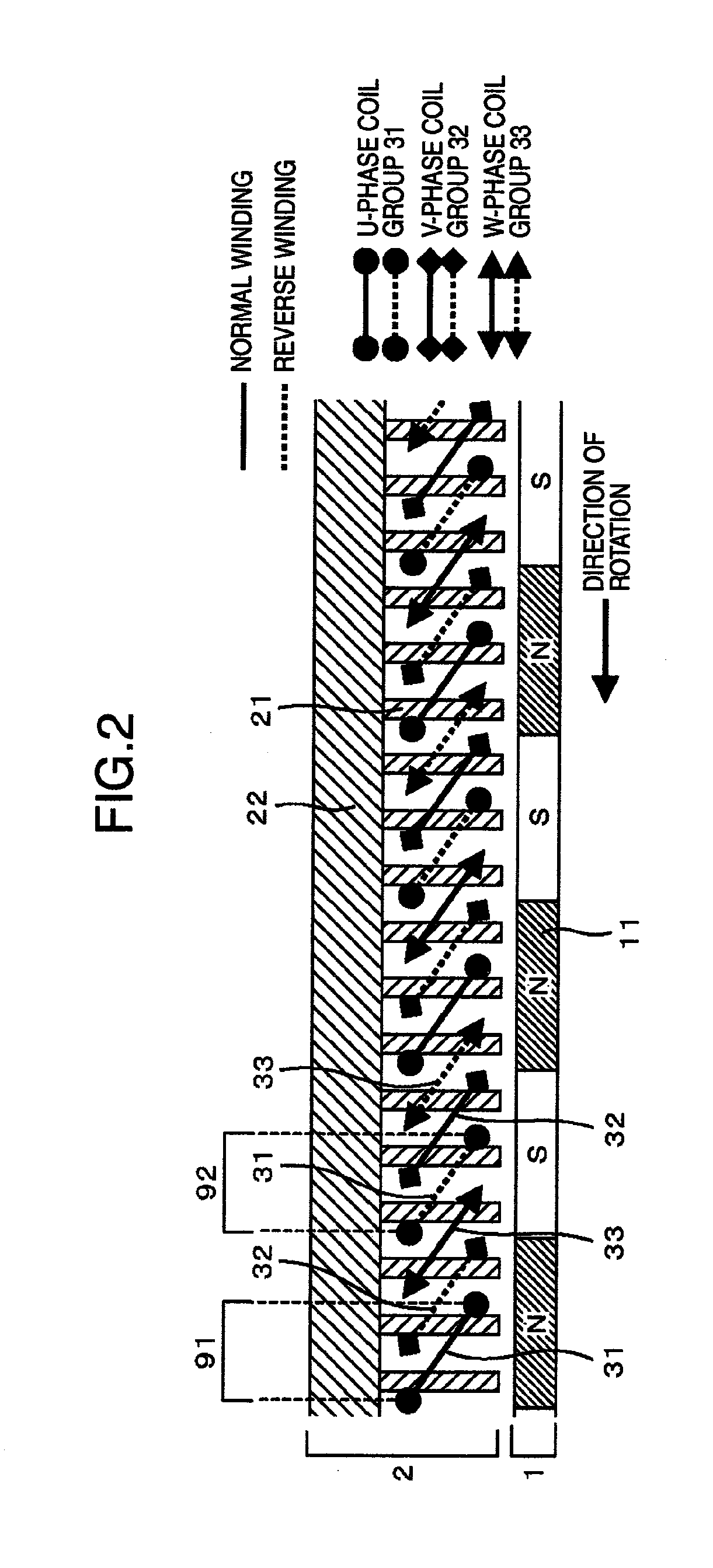
[0083]FIG. 11 schematically shows an electric motor, with its air gap portion developed linearly along the circumferential direction of the rotor. Except the items described below, this embodiment is the same as the embodiments described above.
[0084]It is preferable to construct the windings of the three-phase system A and the windings of the three-phase system B equivalently in the sense of electric circuit element. By doing so, the higher harmonic components of electromagnetic force can be effectively suppressed. When this winding structure is employed in a generator, the output current becomes uniform so that the ripples in the resultant output current can be reduced. To obtain this effect, each coil unit spanning teeth in the circumferential direction is slanted as viewed in the direction along the rotor shaft, as shown in FIG. 11. Thus, the windings of each of the three-phase systems A and B form stator magnetic poles for the respective phases U, V and W. Two coil units of a ph...
PUM
 Abstract
Description
Claims
Application Information
 - R&D
- Intellectual Property
- Life Sciences
- Materials
- Tech Scout
- Unparalleled Data Quality
- Higher Quality Content
- 60% Fewer Hallucinations
Browse by: Latest US Patents, China's latest patents, Technical Efficacy Thesaurus, Application Domain, Technology Topic, Popular Technical Reports.
© 2025 PatSnap. All rights reserved.Legal|Privacy policy|Modern Slavery Act Transparency Statement|Sitemap|About US| Contact US: help@patsnap.com


