Eureka AIR delivers breakthrough ideas for toughest innovation challenges, trusted by R&D personnel around the world.

Measurement of hydraulic conductivity using a radioactive or activatable tracer

a tracer and radioactive technology, applied in the direction of instruments, surveying, borehole/well accessories, etc., can solve the problems of inaccuracy, complicating the use of the pump testing method, and affecting the accuracy of the measurement of hydraulic conductivity, so as to achieve the effect of determining the conductivity of liquids in an underground environment more accurately

Inactive Publication Date: 2009-09-17
AUSTRALIAN NUCLEAR SCI & TECH ORGANISAT
View PDF8 Cites 27 Cited by
  • Summary
  • Abstract
  • Description
  • Claims
  • Application Information

AI Technical Summary

Benefits of technology

[0156]One advantage of the invention is that hydraulic conductivity of a liquid in an underground environment may be determined more accurately than with the pump test method. It has been found, using the method in accordance with the invention, that an incremental resolution of as little as about 10 cm is obtainable for an uncased borehole, without packers to isolate each injection zone. Whereas the standard pump flow test resolution is of the order of meters, if not more. A further advantage of the method according to the invention is that the need for multiple boreholes to determine hydraulic conductivity is obviated.
[0157]The invention also extends to a spectral gamma radiation bore-logging tool whenever used in applying a method in accordance with the invention. The spectral gamma ray bore-logging tool may also conveniently comprise a suitable source of radioactivity. It may thus be adapted to emit radiation of a type that is capable of causing a non-radioactive substance to become radioactive. Thus, it may be capable of emitting neutrons capable of penetrating into the nuclei of atoms in the environment of the borehole. Depending on the nature of the materials and formations in the borehole environment, neutrons could have a penetrating range up to about 1 m.

Problems solved by technology

The measurement of hydraulic conductivity according to the pump testing method is subject to inherent inaccuracies.
A further disadvantage of this method is that, in existing boreholes lined with casings, there are either no holes through the casing in the zone of interest or, where slots or holes have been provided, they are located only in predetermined regions.
Because of the influence of the positions of such holes on the flow of liquids in the borehole and its environment, these and other factors complicate the use of the pump testing method and contribute to its inaccuracy.
Typically, this means one low spatial resolution value per well, which may not accurately represent the true variability of hydraulic conductivity at that site.
However, the costs associated with the application of this method could be high if the boreholes have to be drilled specially for this purpose.
The method also requires many analyses to detect the tracer in adjacent boreholes, which is laborious, time consuming and costly.
This method is clearly unsuitable for the determination of liquid flows in a three dimensional environment, particularly where it is important to determine the direction of flow as well as the hydraulic conductivity.
The method is unsuitable for the measurement of flow velocities below about 10 mm per second.
Attenuation of radiation, which occurs as a result of Compton scattering, is considered in respect of only one energy level, and is therefore inaccurate and unreliable.

Method used


Image

  • Measurement of hydraulic conductivity using a radioactive or activatable tracer
  • Measurement of hydraulic conductivity using a radioactive or activatable tracer
  • Measurement of hydraulic conductivity using a radioactive or activatable tracer

Examples


case 1

niform Distribution” Case

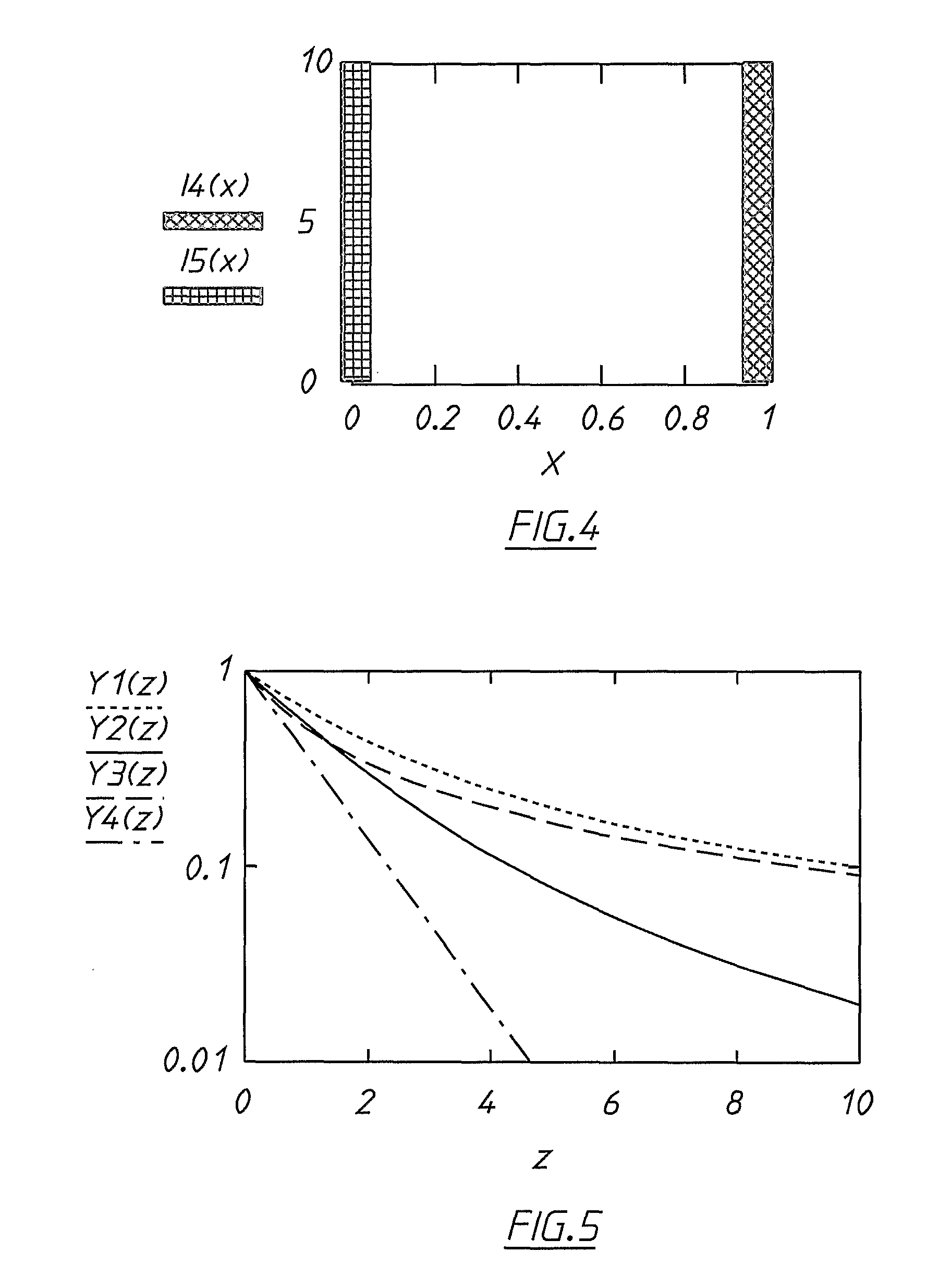
[0212]In this case, the tracer is assumed to be uniformly distributed over the interval 00=M / l remaining constant, where M is the total “mass” of radioactive material and l is the distance. The following equation may then be derived:

Itot(l)=Mμl(1--μl)-tln2 / τ.(7)

[0213]This relationship is illustrated in FIG. 2.

[0214]In normalised variables, the aforementioned relationship may be expressed as follows:

Y1(z)=1z(1--z),whereY1≡ItotMtln2 / τ,andz≡μl.(8)

case 2

ast Injection” Case

[0215]For this case, it is assumed that the tracer is distributed linearly with the density of distribution I0(x)=2Mx / l2 at 0

[0216]The intensity of radiation received at the borehole can be expressed as follows:

Itot(l)=2Mμ2l2[1-(1+μl)-μl]-tln2 / τ.(9)

[0217]This relationship is illustrated in FIG. 2.

[0218]Using the same normalised variables as before, it can be expressed as follows:

Y2(z)=2z2[1-(1+z)-z].(10)

case 3

iffusive Intrusion” Case

[0219]For this case, it is assumed that the tracer is distributed exponentially over the distance l as follows: I0(x)=(M / l)e−x / l.

[0220]The intensity of radiation received at the borehole can be expressed as follows:

Itot(l)=M1+μl-tln2 / τ.(11)

[0221]Using the same normalised variables as before, it can be represented as follows (see FIG. 2):

Y3(z)=11+z(12)

[0222]The three different distribution functions considered above are depicted in FIG. 3.

[0223]However, as can be seen in FIGS. 2 and 3, the dependence of gamma radiation counts on distance is qualitatively the same for all three distribution functions, with the result that the nature of the assumption as to what the distribution profile is, is relatively unimportant. In all three cases, the signal received by a detector placed in the borehole, decreases with increasing distance over which the tracer is distributed.

[0224]The decay rate of the received signal decreases faster (slower) if a maximum of distribution ...


PUM


Abstract

A method of determining the distance, from a reference point, of a tracer emitting radiation comprising a first component emitted at a first known energy level and a second component emitted at a second known energy level, the intensity of a penetrating portion of the first component that penetrates a substance between the tracer and the reference point and the intensity of a penetrating portion of the second component of the radiation that penetrates the substance being a function of the rate of gamma radiation emission of the tracer as well as of the distance of the tracer from the reference point, the method comprising: a) measuring the intensity of the first penetrating portion and the intensity of the second penetrating portion; b) determining the ratio of the intensity of the first penetrating portion to the intensity of the second penetrating portion; and c) determining the distance of the tracer from the reference point.

Description

TECHNICAL FIELD[0001]The present invention relates to the measurement of conductivity of liquids in underground formations. More particularly, the invention relates to a method of determining the distance from a borehole of a volume of liquid in an underground environment of the borehole, to a method of determining hydraulic conductivity of a liquid in an underground environment of a borehole, to a system for determining hydraulic conductivity of a liquid in an underground environment of a borehole, and to an apparatus for determining the distance from a borehole of a volume of liquid in an underground environment of the borehole.[0002]The invention further relates to a bore-logging tool adaptable for use in determining the distance, from a borehole, of a volume of liquid in an underground environment of the borehole. The invention also relates to a tool and a kit adaptable for use in determining hydraulic conductivity.BACKGROUND OF THE INVENTION[0003]One method that is currently us...

Claims


Application Information

Patent Timeline
IPC IPC(8): G01V5/04E21B47/10
CPCG01V5/101E21B47/1015E21B47/11E21B47/111
Inventor WARING, CHRISTOPHER LESLIEAIREY, PETER LEWISSTEPANYANTS, YURY A.
Owner AUSTRALIAN NUCLEAR SCI & TECH ORGANISAT
Why Eureka
Eureka Blog
Learn More