
System for continuous optimization of wastewater treatment

a wastewater treatment and optimization technology, applied in television systems, other chemical processes, separation processes, etc., can solve the problems of difficult real-time monitoring of heavy metal concentration levels, special attention required for removal, and inability to accurately monitor the concentration of heavy metals, etc., to reduce the time needed for plant operators, reduce the effect of treatment chemical consumption and reducing the amount of treatment chemical

Active Publication Date: 2009-09-17
BOWERS JR GREGORY SCOTT
View PDF9 Cites 12 Cited by
  • Summary
  • Abstract
  • Description
  • Claims
  • Application Information

AI Technical Summary

Benefits of technology

[0026]It is a more general object to provide an improved wastewater treatment which effectively minimizes treatment chemical consumption.
[0027]In providing such improved method and apparatus, it is yet a further object of this invention to provide same with the ability to change a chemical treatment solution feed rate so as to automatically match varying demands of the wastewater chemistry, thereby resulting in such reduced treatment chemical consumption In providing such an automatically operative system, it is an object to provide a system which can be practically operated substantially continuously, and so as to greatly reduce a plant operators time needed to manage and maintain same.
[0028]It is another more general object of the present invention to provide for improved wastewater treatment which permits continuous and automatic achievement of a predetermined set point of heavy metal concentration in solution (such as legislatively mandated levels in parts per million or fractions thereof). It is a more particular object to provide such a system which is effective in achieving such objects despite even wide variations in the heavy metal concentrations, such as may occur from entirely unanticipated dumps of relatively high heavy metal concentrations into the wastewater flow.
[0030]It is yet another object of the present invention to provide such an improved waste water treatment system, which is effective for controlling the consumption of a wide variety of available precipitating agents.
[0032]It is yet another general object of the present invention to provide for improved wastewater treatment which effectively distinguishes between metals in solution which are chelated and / or complexed, and those which are non-chelated and / or non-complexed, so as to enable efficient utilization of a precipitating agent for the chelated and / or complexed metals. It is a further object to provide for controlled feeding of such precipitating agent to the wastewater to be treated, instead of merely allowing feeding of such precipitating agent at a calculated rate based on anticipated maximum heavy metal concentrations.
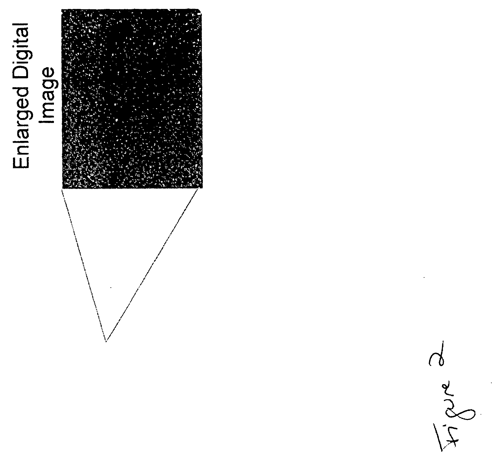
[0036]Preferably, the means for analyzing the images in order to determine the necessity for injecting wastewater treatment chemicals into the wastewater stream is a computer and the means for injecting wastewater treatment chemicals into the wastewater stream is controlled by the computer, thereby limiting the need for operator involvement. Preferably, the computer determines the particle sizes of differing moieties in the wastewater stream by the grouping of pixels of similar color and appearance and it determines the concentrations of differing moieties in the wastewater stream by the spacing between the various pixels.

Problems solved by technology

Chelating and / or complexing tends to cause such metals to remain in solution, and thus require special attention for their removal.
While concentration variations can in general be expected, monitoring of and reacting to specific variations is problematic.
Since effective real time monitoring of heavy metal concentration levels has heretofore generally proven difficult, such treatment chemical feeding (i.e. the feed rate of precipitating agents) is typically set at a compromise level, such as for precipitating the maximum expected concentration of heavy metals.
Such a compromise setting creates an excess amount of sludge, which sludge may often be classified as a hazardous waste.
Moreover, since the cost of the treatment chemicals is not insignificant, wasteful overfeeding thereof is costly.
However, such a manual adjustment merely alters the set feed rate in accordance with periodic reassessments of the anticipated maximum concentration, and does nothing to eliminate excess sludge production and excessive and costly chemical usage caused by differences between actual concentration levels and the anticipated maximums thereof.
Moreover, short-term spikes can still occur, meaning that inadequately treated wastewater can be nonetheless discharged.
Such occurrences are particularly problematic where applicable laws regulate the permissible discharge concentration levels, such as to certain fractional parts per million or certain parts per million.
For example, a totally unexpected occurrence of heavy metals in the wastewater can go unchecked, thereby causing the plant to exceed permissible discharge levels.
For example, maintenance personnel might empty mop buckets or the like containing chelated heavy metals picked up from the floor of the facility, which could cause a heavy metal concentration spike in the wastewater at a time whenever commercial activity in the plant is nil, and precipitating agent feed pumps may be switched off.
The plant is nonetheless responsible for its wastewater discharge, though no effective continuous monitoring systems for preventing such undesirable discharges may be available.
While such a controller may be effective for metals which may be precipitated through such pH inducement, heavy metals which are chelated and / or complexed generally will not be precipitated with such pH level control.
Thus, the monitoring and treatment problems noted above persist, and may be compounded where a changing mix of chelated and non-chelated metals is presented for treatment.
However, unnecessary sludge production is caused by precipitating metals in such a manner which could have otherwise been precipitated through pH level control (as generally discussed above).
One particular limitation of such a system is that it cannot distinguish between, for example, chelated and non-chelated metals, and must therefore feed precipitating agent until there is an excess of such agent present in the water.
Thus, there is no effective prevention of excess sludge generation or wasteful chemical usage.
Another limitation of a waste treatment system utilizing an oxidation reduction potential (ORP) probe is that the probe operation involves an electrical measurement which is affected by changes in the pH level of the wastewater, the amount of total dissolved solids therein, the oxidizer concentration, and the amount of chelated metal in the wastewater.
Thus, an ORP probe system is inherently ineffective for use in providing close control of the feeding of chemical treatment solutions into wastewater treatment systems.
The newly formed agglomerated particles are quite fragile and can be broken apart by shear forces during mixing.
Care must also be taken to not overdose the polymer as doing so will cause settling / clarification problems.
As a result, increasing the dosage will increase the tendency of the floc to float and not settle.
However, the images generated and analyzed by the image recognizing means of the '269 patent are limited to shapes, sizes and luminance of the particles being photographed, essentially black and white photographs with shades of gray.
Thus, the '269 patent fails to provide a system capable of recognizing differing species in a wastewater stream and adjusting the injection of a variety of chemical wastewater treatment agents in response.

Method used


Image

  • System for continuous optimization of wastewater treatment
  • System for continuous optimization of wastewater treatment
  • System for continuous optimization of wastewater treatment

Examples


Embodiment Construction

[0047]In conjunction with the following description of exemplary embodiments of this invention, it is to be understood that features and aspects of this invention may be variously practiced in combination with a variety of wastewater treatment systems, not all of which are necessarily shown nor explicitly mentioned hereinafter. However, specific exemplary embodiments are presented herewith and discussed in detail below to provide those of ordinary skill in the art with an adequate disclosure of this invention for practicing same, either as shown and discussed herein or as adapted by such persons from time to time for conformance with their particular requirements.

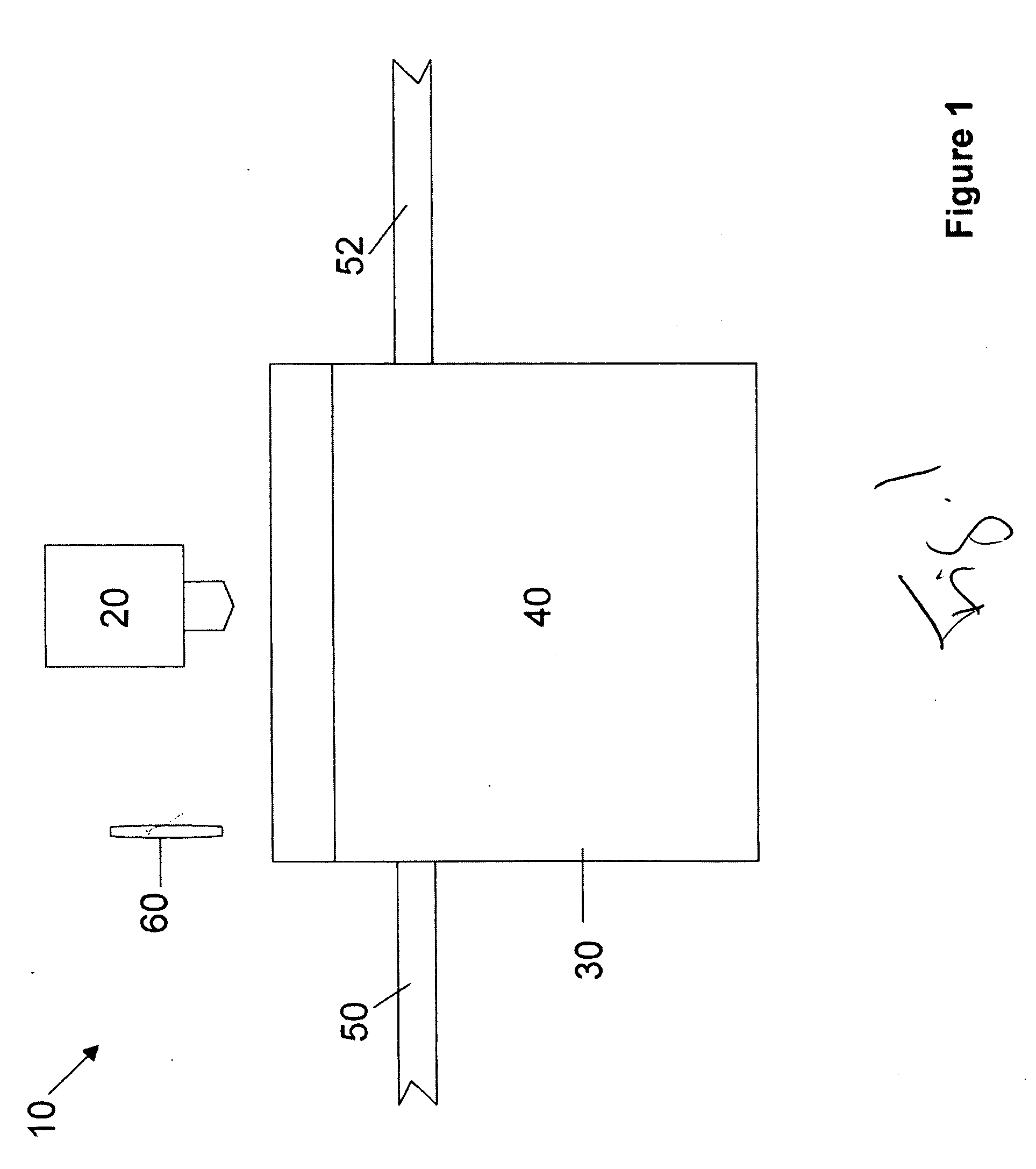
[0048]Thus, FIG. 1 schematically illustrates the system 10 of the present invention in which high resolution digital camera 20 is positioned above holding tank 30 containing wastewater 40. Pipe 50 flows into the holding tank and pipe 52 carries the wastewater stream from the holding tank. It should be noted that the term “h...


PUM

PropertyMeasurementUnit
sizeaaaaaaaaaa
particle sizesaaaaaaaaaa
concentrationsaaaaaaaaaa

Abstract

A system for controlling the injection of wastewater treatment chemicals into a wastewater treatment stream includes a holding tank for collecting and holding wastewater being treated, a camera positioned for making images of the wastewater in the holding tank, means for automatically making the images of the wastewater in the holding tank at scheduled intervals, means for analyzing the images in order to determine the necessity for injecting wastewater treatment chemicals into the wastewater stream, comprising measuring the size, distribution and number of pixels of differing colors and appearances, such that pixels of differing colors and appearances represent differing moieties in the wastewater stream including unreacted waste products and unreacted wastewater treatment chemicals, and means for injecting wastewater treatment chemicals into the wastewater stream responsive to the analysis of the images indicating the necessity of such injection.

Description

[0001]The present application claims the benefit of prior provisional U.S. Ser. No. 61 / 069,733, filed Mar. 17, 2008.FIELD OF THE INVENTION[0002]The present invention is generally directed to a system for adjusting the dosage of wastewater treatment chemicals in an automated fashion requiring limited operator oversight. More particularly, the present invention is directed to such a system in which photography, most preferably digital photography, is employed to monitor the wastewater stream.BACKGROUND OF THE INVENTION[0003]Industrial wastewaters commonly include a variety of contaminants which require treatment (i.e., removal) even before the wastewater can be discharged from the plant site. The nature of the wastewater contaminants is in large part dependent on the commercial processes practiced in the plant. Accordingly, there is great variety in the nature of wastewater contaminant problems. Moreover, the matrix (i.e., makeup) of wastewater even at a given commercial site will usu...

Claims


Application Information

Patent Timeline
Patent Type & Authority Applications(United States)
IPC IPC(8): B01D35/00
CPCC02F1/50C02F1/5209C02F2209/005C02F2101/22C02F2209/00C02F2101/20
Inventor BOWERS, JR., GREGORY SCOTT
Owner BOWERS JR GREGORY SCOTT
Learn More