Pitching machine
a pitching machine and pitching technology, applied in the field of sports equipment, can solve the problems of ineffective self-practice for batters, too limited time, and the cost of most dedicated pitching machines, and achieve the effect of safe and convenient operation
- Summary
- Abstract
- Description
- Claims
- Application Information
AI Technical Summary
Benefits of technology
Problems solved by technology
Method used
Image
Examples
first embodiment
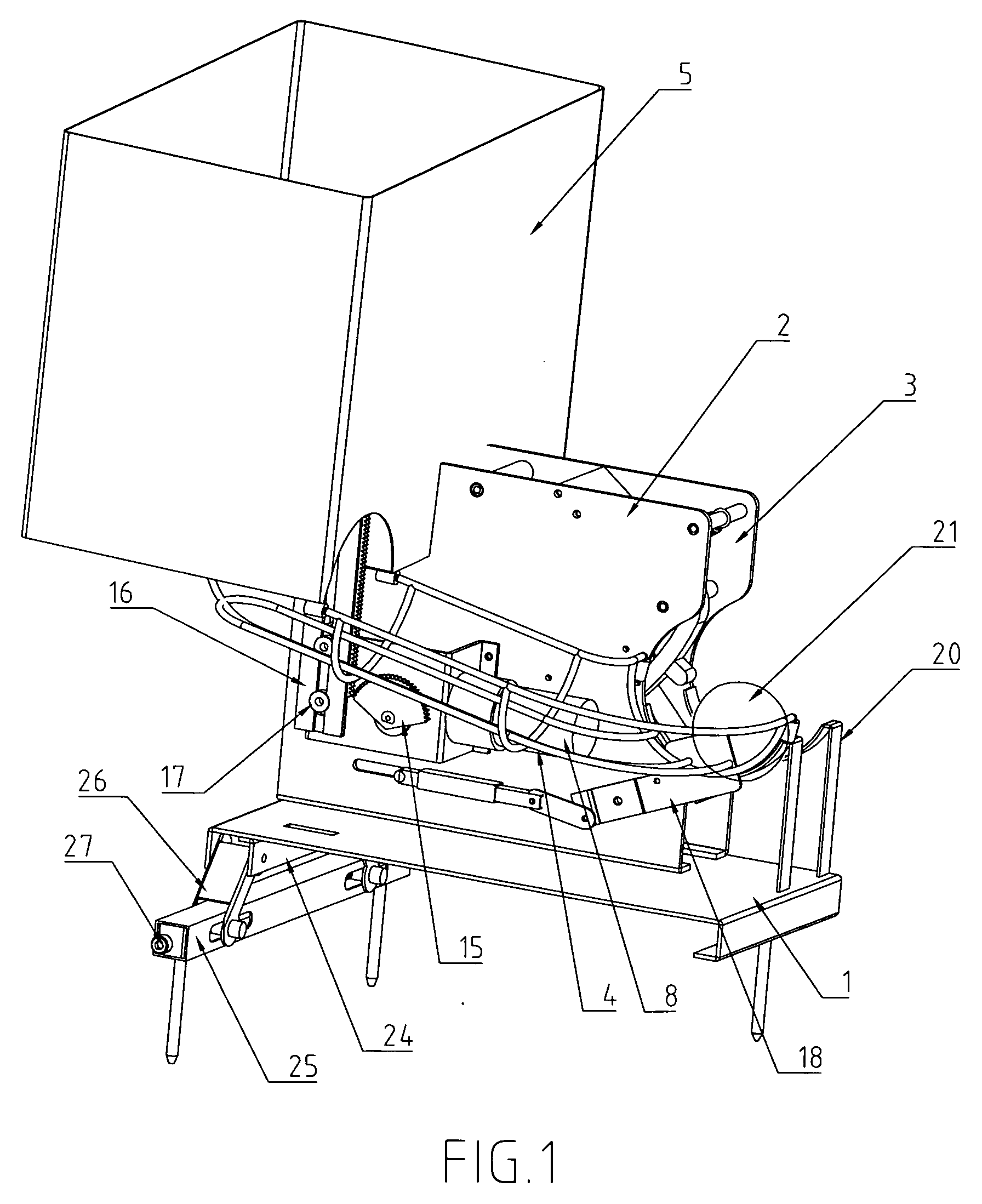
[0044]Referring to FIGS. 1 to 6, a pitching machine according to the present invention is illustrated, wherein the pitching machine comprises a pedestal, a guide channel 4, a ball rack 20, a hopper 5, and a ball hitting mechanism. The pedestal includes a base plate 1, a left side plate 2, and a right side plate 3. To ensure all the balls in the hopper 5 can flow along the guide channel 4 to the ball rack 20, the bottom of the hopper 5 has a funnel shape that the bottom thereof is extended inclinedly and the outlet opening of the hopper 5 is formed at the lowest point of the bottom of the hopper 5. The outlet opening of the hopper 5 is connected to the guide channel 4, and the outlet opening of the guide channel 4 is connected to the ball rack 20. When the hopper 5 is filled up with balls, it can constantly supply the balls to ball rack 20 to retain the ball at the ball rack 20. The ball hitting mechanism comprises a striking rod 6, a resilient element 7 such as a spring, and a strik...
second embodiment
[0050]The pitching machine illustrated in the present invention further comprises a feeding mechanism which comprises an L-shape ejection plate 29, an axis and an ejection rod 30. The axis goes through the bearing holes on the right side plate 2 of pedestal, with one end mounted with the L-shape ejection plate 29 and the other end with the ejection rod 30. As the crank 28 rotates every cycle in a circular manner, the respective end of the crank 28 with the roller 28a presses the ejection rod 30 downwards and levers the L-shape ejection plate 29 on the other end of the axis upwards. The top end of the L-shape ejection plate 29 extends into the hopper to free one of the balls from the hopper.
[0051]FIGS. 10 to 20 illustrate a third embodiment of the present invention. Identical with the structural principle of a first embodiment, the principal part in a third embodiment also comprises a pedestal, a guide channel 4, a ball rack 20, a hopper 5, and a ball hitting mechanism. The pedestal ...
third embodiment
[0053]The feeding mechanism in the third embodiment includes an ejection plate 16 that is mounted under the outlet opening of the bottom of the hopper 5 and driven by the motor 8 to reciprocate up and down in the sliding channel of pedestal. The momentum output by the motor 8 is faded first by the bevel gears 13 and 14 and then by a pair of cylindrical gears 31 and 32. A crank 33 on the cylindrical gear 32 actuates a connecting rod 34 which then drives the ejection plate 16 to reciprocate up and down in the sliding channel of pedestal. The top end of the ejection plate 16 moves up and down in the hopper 5 to free one of the balls from the hopper 5 such that the ball is guided to flow along the guide channel 4 smoothly without getting stuck.
[0054]The controlling mechanism illustrated in a third embodiment of the present invention comprises a poke rod 36, a drive wire 37 and a controlling member. The poke rod 36 is mounted on the left side plate 2 of a support 39 with its middle part ...
PUM
 Abstract
Description
Claims
Application Information
 - R&D
- Intellectual Property
- Life Sciences
- Materials
- Tech Scout
- Unparalleled Data Quality
- Higher Quality Content
- 60% Fewer Hallucinations
Browse by: Latest US Patents, China's latest patents, Technical Efficacy Thesaurus, Application Domain, Technology Topic, Popular Technical Reports.
© 2025 PatSnap. All rights reserved.Legal|Privacy policy|Modern Slavery Act Transparency Statement|Sitemap|About US| Contact US: help@patsnap.com


