
Energy and multimedia data transport network and rail

a technology for energy and multimedia data, applied in closed circuit television systems, television systems, coupling device connections, etc., can solve the problems of affecting the safety of other passengers, notably boredom, and a large amount of moving around the aircraft, and achieves the effect of high upgrade potential and inexpensive implementation

Inactive Publication Date: 2009-09-10
THALES SA
View PDF4 Cites 8 Cited by
  • Summary
  • Abstract
  • Description
  • Claims
  • Application Information

AI Technical Summary

Benefits of technology

[0061]The invention has notably the main advantages of exhibiting a modular structure adaptable to various configurations and having high upgrade potential. The invention also presents the advantage of being inexpensive to implement.

Problems solved by technology

Nowadays, one of a traveller's concerns on a long-haul aircraft is notably boredom during the long hours of flight.
Travellers, passengers on long-haul aircraft, when they become bored, have a tendency to move around the aircraft a great deal and to call upon the onboard flight personnel, sometimes to the detriment of the safety of the other passengers.
Onboard an aircraft, certain constraints prevent the use of technologies commonly used in a domestic or office environment such as: Ethernet networks, 220-volt mains sockets.
The use of connectors secured to the structure of the aircraft makes it difficult or indeed impossible to change seat configurations in the aircraft.
Connectors may then be unused and therefore exposed to deterioration caused by dust, impacts, liquids.
T his therefore generates cost overheads in the production of the aircraft.
Moreover, risks of seizing of the mobile support may render the support unusable after a short time.
A mobile support such as this therefore requires considerable and expensive maintenance.
The flexible cables notably pose reliability problems in the case where a connector is located far from a seat: the cables may be impaired during changes of seats, or by the feet of the passengers.
Such first and second solutions also exhibit the drawback of using many cables, thus limiting the capabilities of the network structure in terms of data and power transport, with the risk of greatly increasing the dead weight.
However, optical fibres do not make it possible to convey power and are very fragile, so increasing the maintenance costs of the third solution.
Specifically, the power radiated by the radio network does not make it possible to supply the terminals, floor cabling is therefore required.
Moreover, the total bandwidth of a radio network for the entire aircraft may be insufficient to transmit, for example, a large number of films simultaneously.
Use of radio networks may also give rise to risks of disturbance to the aircraft flight equipment.
Moreover, the standards in regard to electromagnetic radiation are very strict in certain countries.
A radio network therefore cannot be embedded onboard all aircraft in a standard manner.
Finally, such a radio network might also not be satisfactory in terms of services offered, on account notably of the fact that the available bandwidth is too low.

Method used


Image

  • Energy and multimedia data transport network and rail
  • Energy and multimedia data transport network and rail
  • Energy and multimedia data transport network and rail

Examples


first embodiment

[0134]The conductor 62 can, in a first embodiment, be composed of several parts 620, 621, 622, as represented in FIGS. 6a and 6b.

[0135]A first part 620 of the conductor 62 can be of semi-circular cross section with two edges on each side.

[0136]A second part 621 of the conductor 62 can be of parallelepipedal shape. The second part 621 of the conductor 62 is in contact electrically and mechanically with a first edge of the first part 620 of the conductor 62. The second part 621 is able to perform a translation along the first edge of the first part 620 of the conductor 62 while remaining in mechanical and electrical contact with the first part 620 of the conductor 62.

[0137]A third part 622 of the conductor 62 can be of parallelepipedal shape. The third part 622 of the conductor 62 is in contact electrically and mechanically with a second edge of the first part 620 of the conductor 62. The third part 622 is able to perform a translation along the second edge of the first part 620 of t...

second embodiment

[0144]In the second embodiment, the first insulant 63 can be composed of a flexible part, able to deform so as to receive the contacts 68, 69 of the third connection probe 67.

[0145]The internal structure of the coaxial rail 60 can also comprise a first internal conductor 65. The first internal conductor 65 is termed the live of the coaxial rail 60: it emits notably a high-frequency radiation and it conveys a variable voltage. The first internal conductor 65 is of parallelepipedal format. A first end of the first internal conductor 65 is in mechanical contact with the first part of the first insulant 63. A first face of the first internal conductor 65 is in mechanical contact with the third part 632 of the first insulant 63. A second face of the first internal conductor 65 is substantially parallel with the second part 631 of the first insulant 63. The second face of the first internal conductor 65 is separated from the second part 631 of the first insulant 63 by a second space 66. T...

third embodiment

[0207]FIGS. 8a and 8b represent the connection rail 50 and of the second connection probe 55 according to the invention. The connection rail 50 can be embodied by a so-called surface-wave rail 80.

[0208]The surface-wave rail 80 comprises notably one or more conductors 81, 82. FIGS. 8a and 8b represent for example two conducting bars 81, 82. The two conducting bars 81, 82, can be separated from one another by a second insulant 83. The second insulant 83 ensures galvanic isolation of the conductors 81, 82. The second insulant 83 can be embodied by a polymer material.

[0209]The surface-wave rail 80 also comprises one or more strips of piezo-electric materials 84, 85. The piezo-electric strips form for example two piezo-electric tracks 84, 85 making it possible to propagate a mechanical surface wave. The bandwidth of the computer data transmitted is distributed over the piezo-electric tracks 84, 85. The second insulant 83 can ensure protection and mechanical damping between the piezo-elec...


PUM


Abstract

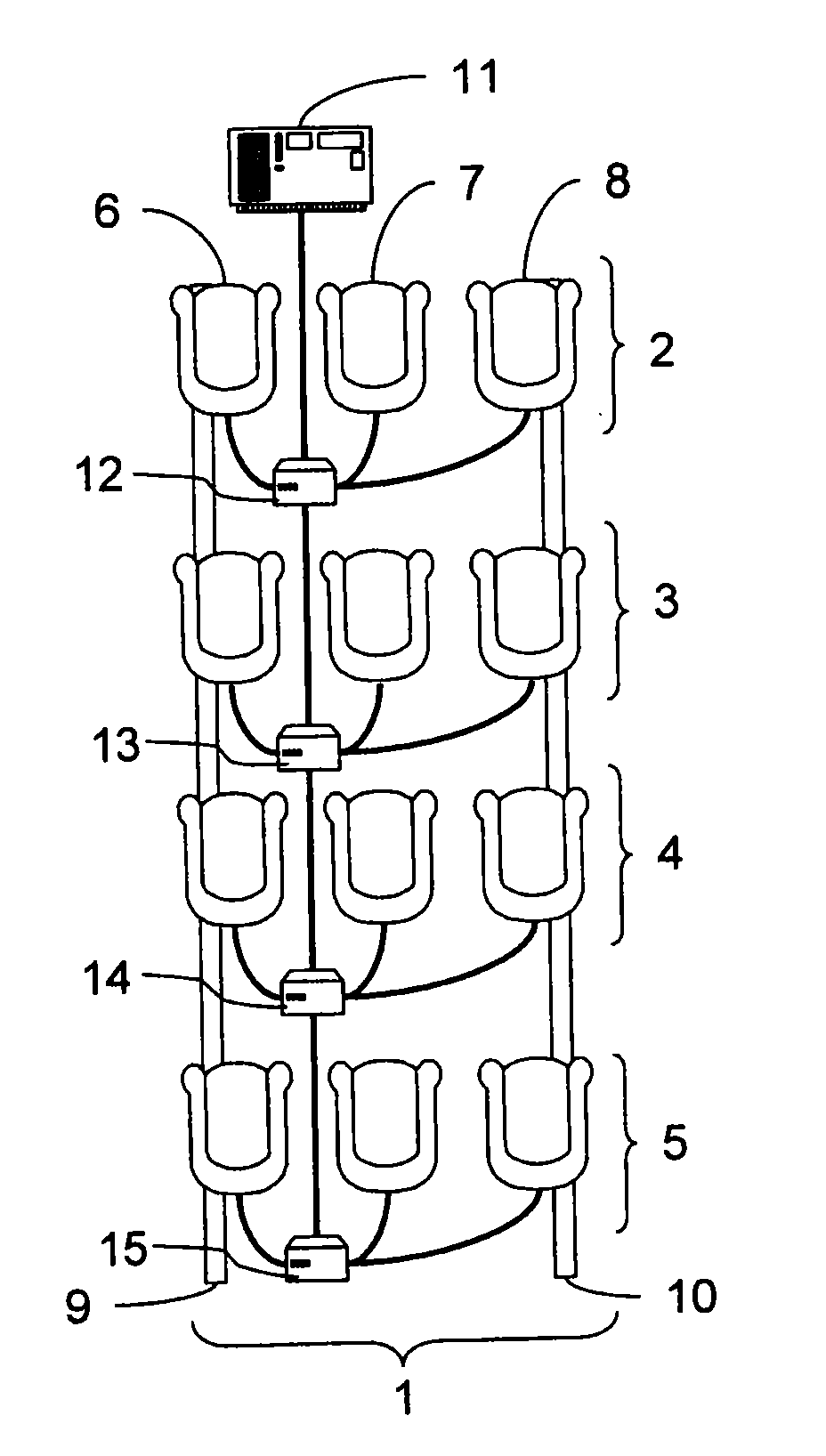
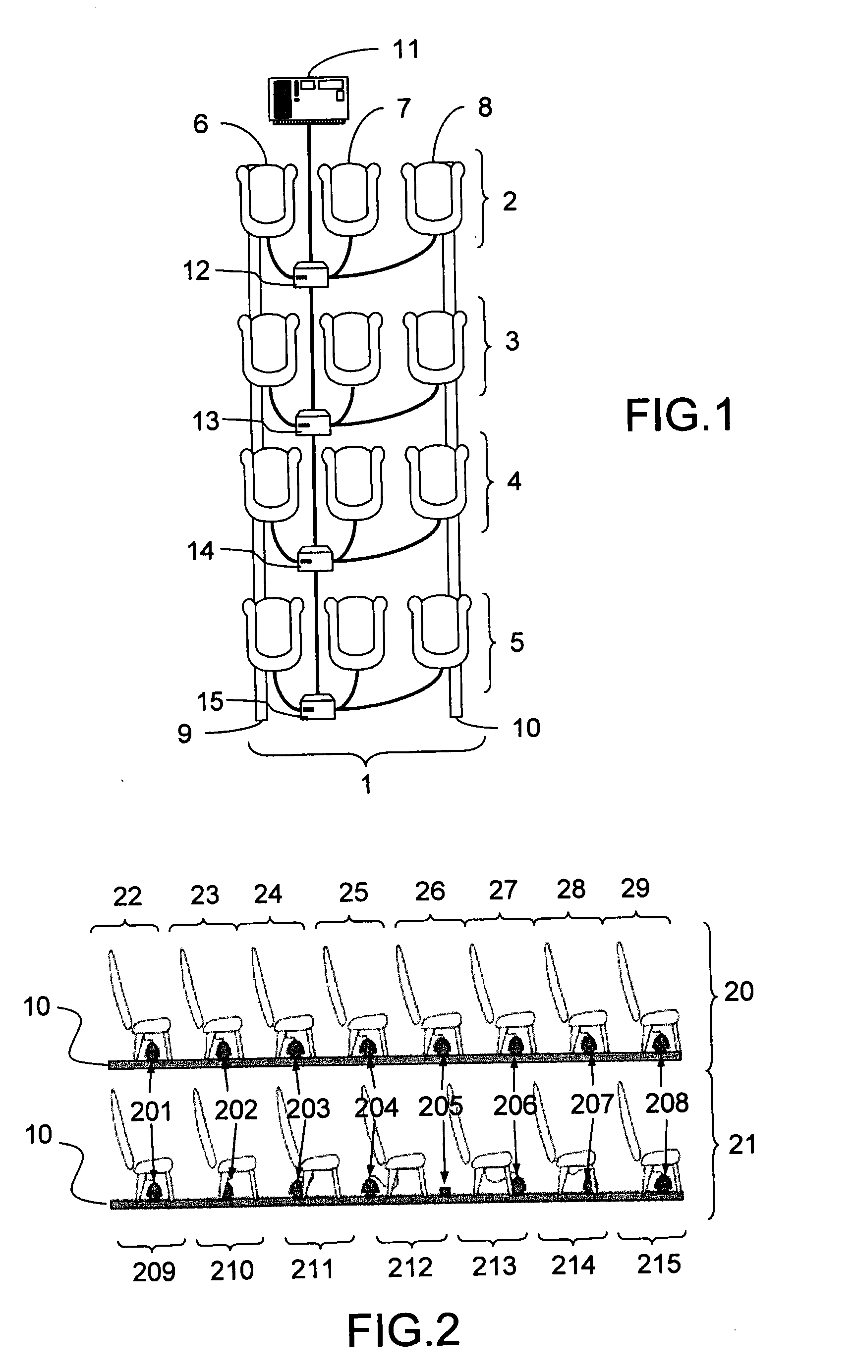
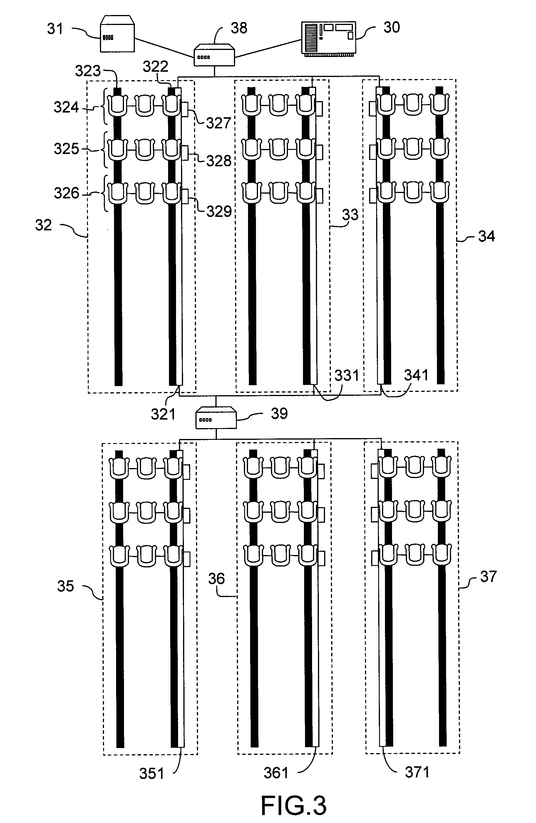
The present invention relates to an energy and multimedia data transport network and rail notably intended for embedded multimedia equipment on board aircraft. The network is connected with at least one data server and at least one energy supply box. The network includes: one or more energy and data transport rails; at least a first interconnection box to interconnect a first energy and data transport rail, the data server and the energy supply box; and a connection module for each terminal or group of multimedia terminals, the connection module including a cable to link a predetermined point of the rail to the associated multimedia terminal or terminals.

Description

CROSS-REFERENCE TO RELATED APPLICATION[0001]The present application claims the benefit of French Patent Application Serial No. 0801183, filed Mar. 4, 2008 which is hereby incorporated by reference in its entirety.BACKGROUND OF THE INVENTION[0002]The present invention relates to an energy and multimedia data transport network and rail notably intended for embedded multimedia equipment on board aircraft. The invention comes within the framework of a package of entertainments offered to passengers of a long-haul flight for example.BRIEF DESCRIPTION OF THE PRIOR ART[0003]Nowadays, one of a traveller's concerns on a long-haul aircraft is notably boredom during the long hours of flight. Travellers, passengers on long-haul aircraft, when they become bored, have a tendency to move around the aircraft a great deal and to call upon the onboard flight personnel, sometimes to the detriment of the safety of the other passengers. It is therefore important to be able to divert the passengers of th...

Claims


Application Information

Patent Timeline
IPC IPC(8): H04N7/18
CPCH01R25/14H04B3/52H04B3/54
Inventor DELWAULLE, JEAN-PIERRE
Owner THALES SA
Learn More