
System for analysis of electrograms

an electrogram and electrogram technology, applied in the field of systems for performing and analysing electrograms, can solve the problems of scarring of the muscle tissue of the heart, increased transverse propagation of the tissue, and refractory area

Inactive Publication Date: 2009-09-10
MEDILEC
View PDF5 Cites 3 Cited by
  • Summary
  • Abstract
  • Description
  • Claims
  • Application Information

AI Technical Summary

Benefits of technology

[0032]The processing system may be arranged to identify first and second rates of variation in signal delay within the range of values of pacing interval, thereby enabling different rates of variation in signal delay to be used in an analysis.
[0092]Thus, the invention in this aspect provides a system which can produce an electrogram indicative of damage in a post-coronary patient, and can analyse the results thereof.

Problems solved by technology

Furthermore, post-coronary patients, i.e. patients who have had a heart attack, for example a coronary thrombosis which has lead to myocardial infarction (AMI or MI) and scarring of the muscle tissue of the heart, may also be at risk of VF.
People with HCM have fibrosis and disarray in the myocardium, which are likely to create delays dues to tortuous conduction, and local block effects; further, the tissue shows an increase in transverse propagation.
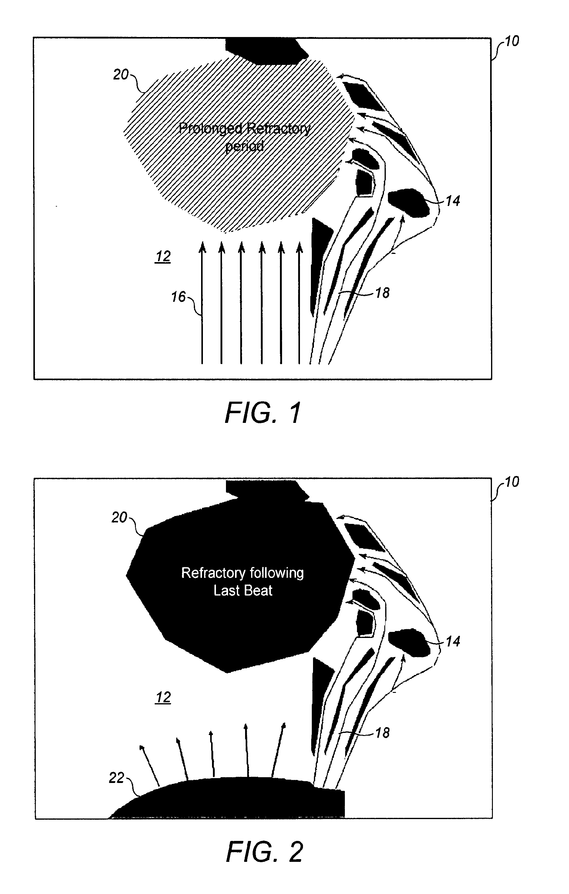
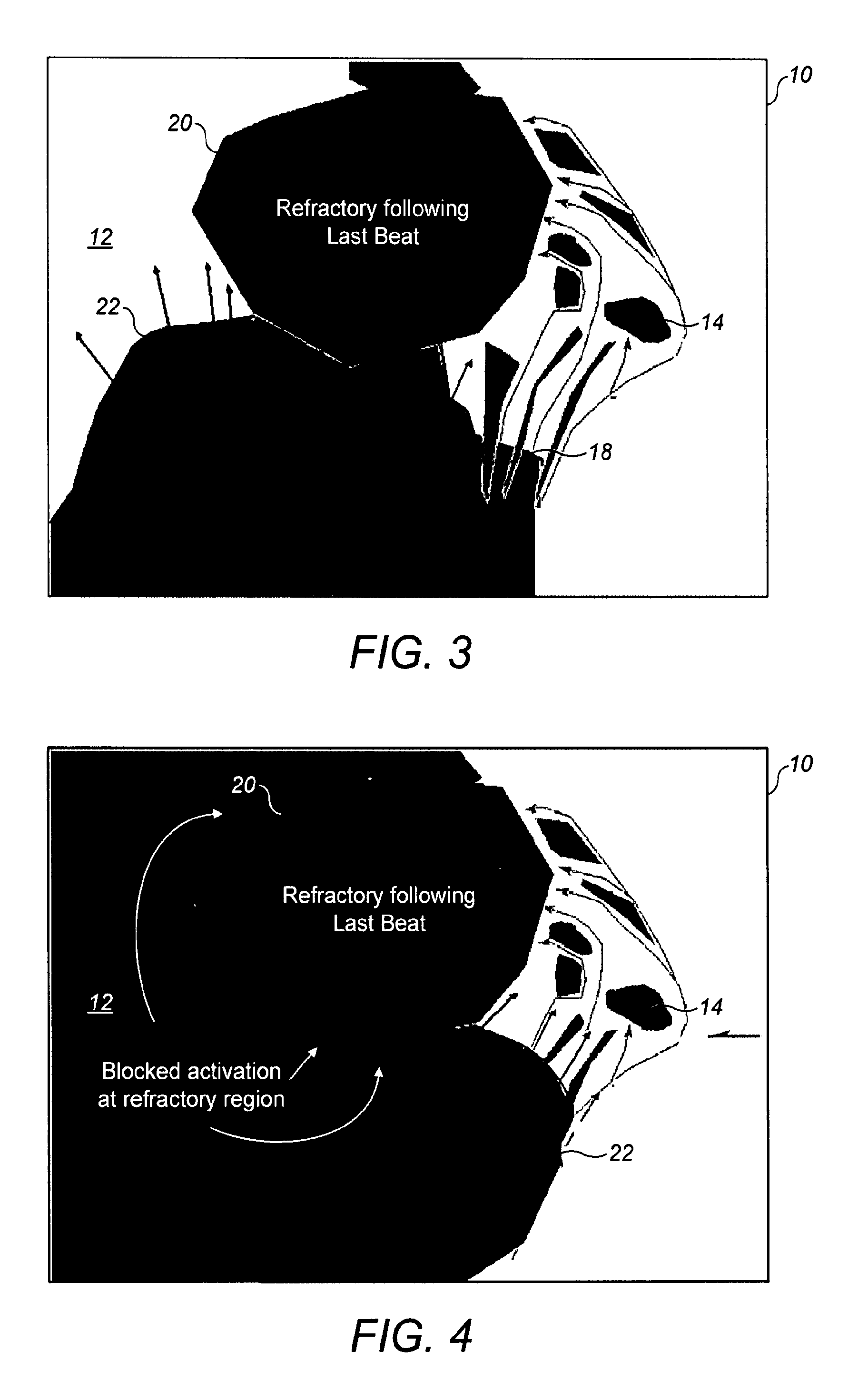
This means that the area is refractory following a previous heart beat.
Some patients, however, do not exhibit myocardial disarray, but are nevertheless prone to VF and to SCD (such as those patients having long QT syndrome (LQTS)); thus, whilst extremely useful, the techniques described in WO94 / 02201 are not sufficiently developed for use in identifying all patients at risk from SCD.
As a result, techniques which involve testing the genotype of a patient cannot be used to determine whether an LQTS patient is susceptible to VF.

Method used


Image

  • System for analysis of electrograms
  • System for analysis of electrograms
  • System for analysis of electrograms

Examples


Embodiment Construction

[0144]As discussed above, the present invention relates to the apparatus for performing and analysing paced electrograms. The present invention includes various methods and arrangements each of which will be discussed in detail in turn.

Processing of Data from Electrograms

[0145]Aspects of the processing of an electrogram 100 produced from stimulating a heart by inserting electrodes therein, for example, as described with reference to FIGS. 9 to 11 will firstly be described. An aspect of particular importance to the interpretation of electrograms is the post-processing of signals so as to reduce noise, so that potentials may be distinguished from noise in the signal, and so that the potentials can be recorded accurately. As is known in the art, signals inherently contain a mixture of noise and data, the noise originating from background sources such as fluorescent lights, X-ray heads, motors, monitors, other equipment commonly found in labs or hospitals, or poor catheter connections. ...


PUM


Abstract

A system for use in analysis of electrograms comprising: an input signal generator (302); an input electrode (304) for applying an input signal to a driving region of a heart (316); an output electrode (306a-c) for receiving an output signal at a driven region of the heart; a processing system (300) operable to receive signals indicative of said recorded value from the output electrode for analysing conduction paths through the heart, wherein the signal generator is operable to generate an input signal comprising a plurality of pulses, being spaced from each other by a pacing interval; and the processing system being arranged to identify signal delay between the input signal and the output signal on the basis of the signal received by the output electrode in relation to the plurality of pulses, and to identify a rate of variation in signal delay over a range of values of pacing interval.

Description

FIELD OF THE INVENTION[0001]The present invention relates to systems for use in performing and analysing electrograms, in particular for the identification of a cardiac condition.BACKGROUND OF THE INVENTION[0002]As is known in the art a human heart comprises pacemaker cells and cardiac muscle cells (myocardium). Cardiac muscle cells are stimulated to contract by an electrical signal. An incident electrical signal causes a cardiac cell to undergo depolarisation. The cell slowly repolarises after it has been stimulated in this way. A contraction in a cardiac muscle cell causes changes to the environment of a neighbouring cell, which can trigger contraction in the neighbouring cell. In this way a signal is transmitted through the muscle of the heart.[0003]In the resting state cells are negative (having a resting potential of about −70 mV). When a muscle cell is stimulated the potential inside increases (i.e. becomes less negative), in a process known as “depolarisation”. Once the cell ...

Claims


Application Information

Patent Timeline
Patent Type & Authority Applications(United States)
IPC IPC(8): A61B5/0432A61B5/0472A61B5/361A61B5/366
CPCA61B5/04023A61N1/37A61B5/7275A61B5/0452A61B5/322A61B5/349A61N1/3702A61B5/24A61B5/361A61B5/36
Inventor SAUMAREZ, RICHARD
Owner MEDILEC
Learn More