
Golf Putting Teaching Device and Method

Inactive Publication Date: 2009-09-10
SCHMUTZ DAVID
View PDF6 Cites 5 Cited by
  • Summary
  • Abstract
  • Description
  • Claims
  • Application Information

AI Technical Summary

Benefits of technology

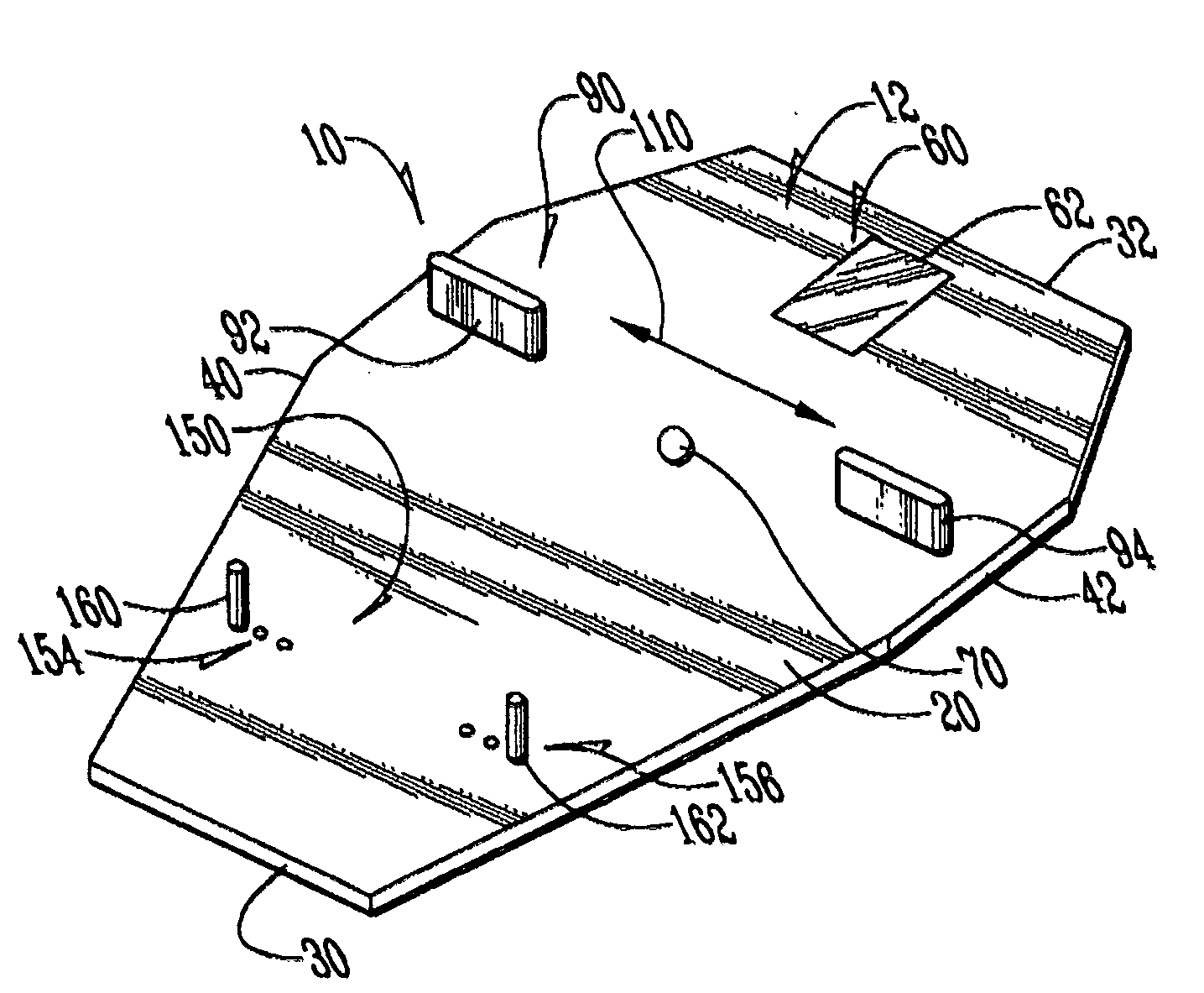
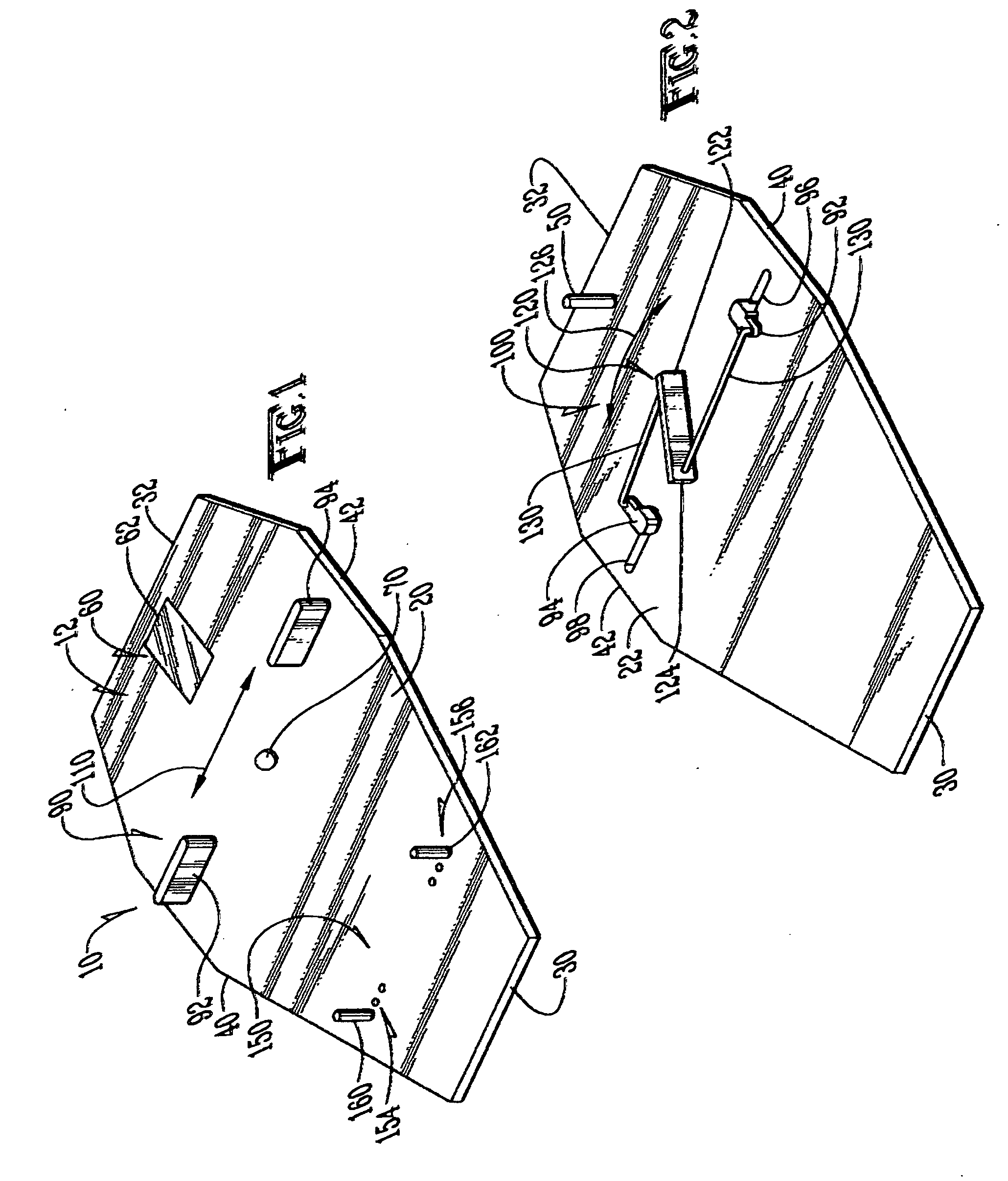
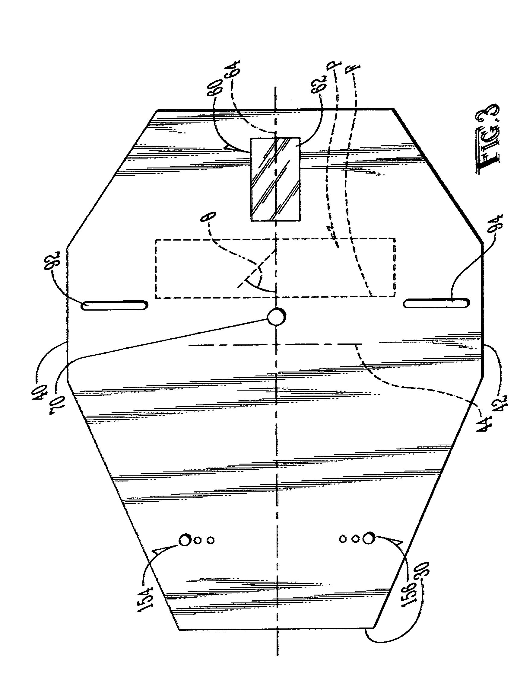
[0019]Specifically, the device embodying the principles of the present invention comprises one sliding adjustable gate that would have two posts, similar to that of two tees, and act as a putter head gate with the putter moving through this head gate during the putting stroke with the head gate being adjustable to accommodate different size putter heads as well as to be able to increase the precision of a putting stroke by being narrowed as desired; a mirror located behind a ball that would allow the golfer to see if their eyes are over the line before starting their stroke; and an adjustable ball gate that is located downstream of the ball being struck so any error in club face angle at impact will be immediately evident. The adjustable ball gate is adjustable from ⅛″ wider than the ball to ½″ wider depending on the skill level of the golfer whereby a golfer can improve his or her skills during practice.

Problems solved by technology

The goal of resting the ball in the hole in as few strokes as possible may be impeded by hazards, such as bunkers and water hazards.
The importance of eye position is that without ones eyes directly over the ball, the golfer cannot properly determine and learn the correct relationship between the putter face and the target.
One of the difficulties with proper alignment is that the human eye, unaided, is not capable of accurately drawing an imaginary target path between the ball and hole and subsequently aligning the putter and his own eye at the required angles to this line to achieve a successful putt.
Firstly there are devices which are mounted on the shaft of a putter which are unsatisfactory because they are generally unwieldy, adversely effect the natural balance of a club, and tend to cause parallax.
Such golf putters are unsatisfactory primarily because they cannot be used under the rules of golf.
It may be useful for a player to train using such a putter however when playing the game he must re-adjust back to his own putter without any sighting device and with the attendent disadvantages of a change in size, shape, weight and particularly balance.
The most important disadvantage of this putter is that it is a separate item of equipment which the player must train with and is not a putter which can be used in play under the rules of golf.
These devices not only suffer from the disadvantages of requiring a separate putter which cannot be used when playing under the rules of golf but are also optically unsatisfactory in that they only partially assist the player in putting the ball correctly in practice.
Optically, these devices are unsatisfactory in that while an inclined mirror on its own is of some assistance in lining a putt up correctly it is not fully accurate as the orientation of the putter face to the ball and the target path between the ball and pin will vary depending on the position of the player's eye.
In addition, the device adversely effects the balance of the club with the result that if a ball is struck by the putter with the device attached with the same force as with the device removed not only will the ball be very unlikely to travel in the same direction but will not travel the same distance.
In addition, the device described can only be mounted on putters having a shaft which extends from either end of the putter.
It would be very difficult to use this device with a bladed putter having a curved back face and it would not be possible to mount such a device on a putter having a shaft which extends from the center of the putter blade—a so called center shafted putter.
In some of these devices, an inclined mirror is not sufficient to achieve the correct orientation of the putting face of a putter to a target line between the ball and pin as this will vary depending on the position of the player's eye.
Further, the device can only be used with a putter blade having a flat continuous rear face.
Further, such a device when attached to a putter adversely effects the normal balance of the putter and not only will a ball struck the same blow with the same putter with and without the sighting device attached be unlikely to travel in the same line but would also not travel the same distance.
Another problem in learning to putt is that greens are not typically flat.

Method used


Image

  • Golf Putting Teaching Device and Method
  • Golf Putting Teaching Device and Method
  • Golf Putting Teaching Device and Method

Examples


Embodiment Construction

[0026]Referring to the figures, it can be understood that the present invention is embodied in a putting stroke practice device 10 which comprises a base plate 12 that is placed on a putting surface and which has a first surface 20 which is a top surface when the base plate is in use, a second surface 22 which is a bottom surface when the base plate is in use, a first end 30 which is a front end when the base plate is in use, a second end 32 which is a rear end when the base plate is in use and a longitudinal axis 34 which extends between the first and second ends. Base plate 12 further includes a first side edge 40, a second side edge 42 and a transverse axis 44 which extends between the first and second side edges. Longitudinal axis 32 is positioned midway between the first and second side edges and defines a proper path for a ball which has been struck by a putter.

[0027]An anchor element 50 is connected at one end thereof to second surface 22 of the base plate and extends into an...


PUM


Abstract

A unitary golf putting teaching device that achieves four goals: teaching proper club head path; teaching proper club face angle at impact; teaching proper posture and proper eye alignment; and teaching green reading.

Description

TECHNICAL FIELD OF THE INVENTION[0001]The present invention relates to the general art of golf, and to the particular field of putting practice aids.BACKGROUND OF THE INVENTION[0002]Golf is a sport in which a player, using several types of clubs, has the objective of getting a ball into each hole on the golf course in the lowest number of strokes. Golf is one of the few ball games that doesn't use a standardized playing area; rather, the game is played on golf “courses,” each one of which has a unique design and typically consists of either 9 or 18 separate holes. Golf is defined in the Rules of Golf as “playing a ball with a club from the teeing ground into the hole by a stroke or successive strokes in accordance with the Rules.”[0003]Golf competition may be played as stroke play, in which the individual with the lowest number of strokes is declared the winner, or as match play with the winner determined by whichever individual or team posts the lower score on the most individual h...

Claims


Application Information

Patent Timeline
IPC IPC(8): A63B69/36
CPCA63B24/0003A63B69/3661A63B69/3676A63B2225/09A63B69/3641A63B2069/3682A63B2225/12A63B69/3682A63B69/3621
Inventor SCHMUTZ, DAVID
Owner SCHMUTZ DAVID
Learn More