
Image processing device and image processing method

a technology of image processing device and image processing method, which is applied in the field of image processing technology, can solve the problems of long time, complex processing, and the types of compression technology employed by image processing device, and achieve the effect of efficient image processing

Inactive Publication Date: 2009-09-10
COLUMBIA PEAK VENTURES LLC
View PDF21 Cites 0 Cited by
  • Summary
  • Abstract
  • Description
  • Claims
  • Application Information

AI Technical Summary

Benefits of technology

[0006]It is an advantage of some aspects of the invention to provide a technology capable of efficiently performing image processing for producing new compression image data based on a part of plural compressed image data.
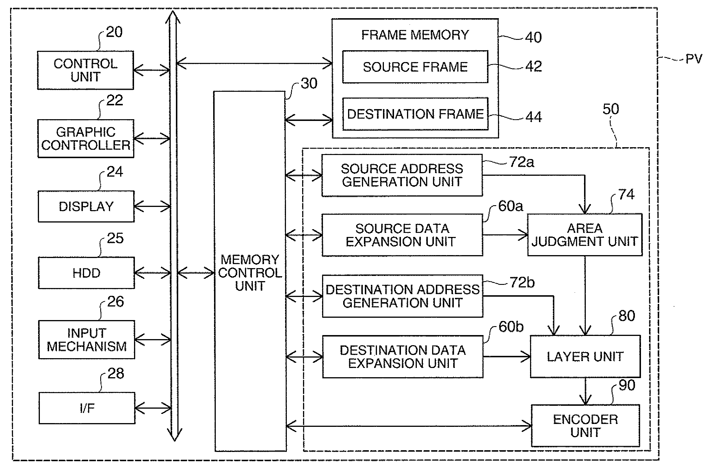
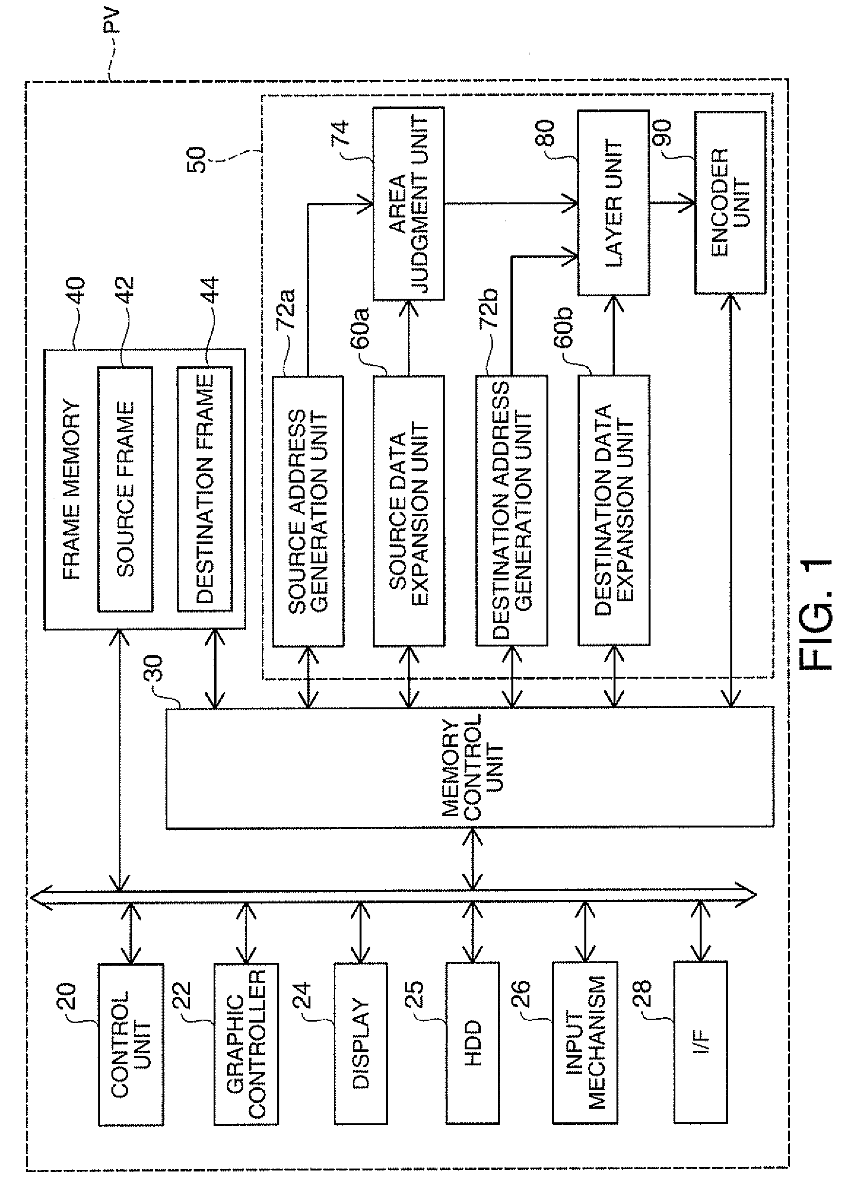
[0008]The image processing device having this structure produces the third part expansion data based on the data produced by expanding a part of the first compression image data and cutting the data in the predetermined range and the data produced by expanding a part of the second compression image data, and combines the compression part data produced by compressing the third part expansion data and a part of the second compression image data to produce the third compression image data. Since the entire compression image data to be processed need not be expanded or compressed, new compression image data can be efficiently produced based on a part of the plural compressed image data. Also, since the entire compression image data to be processed need not be expanded or compressed, the memory capacity can be decreased. Moreover, the volume of data transfer can be reduced, and thus the power consumption of the image processing device can be lowered. The first predetermined area and the second predetermined area may be the same area or different areas. The first expanding unit and the second expanding unit may be substantially the same unit.
[0010]According to the image processing device having this structure, the first producing unit overwrites the cut data of the predetermined range on the predetermined position of the second expansion part data. Thus, the third expansion part data can be easily produced. Alternatively, as another example of data production, the cut data in the predetermined range and the data at a predetermined position of the second expansion part data may be alpha-blended or combined by other methods.
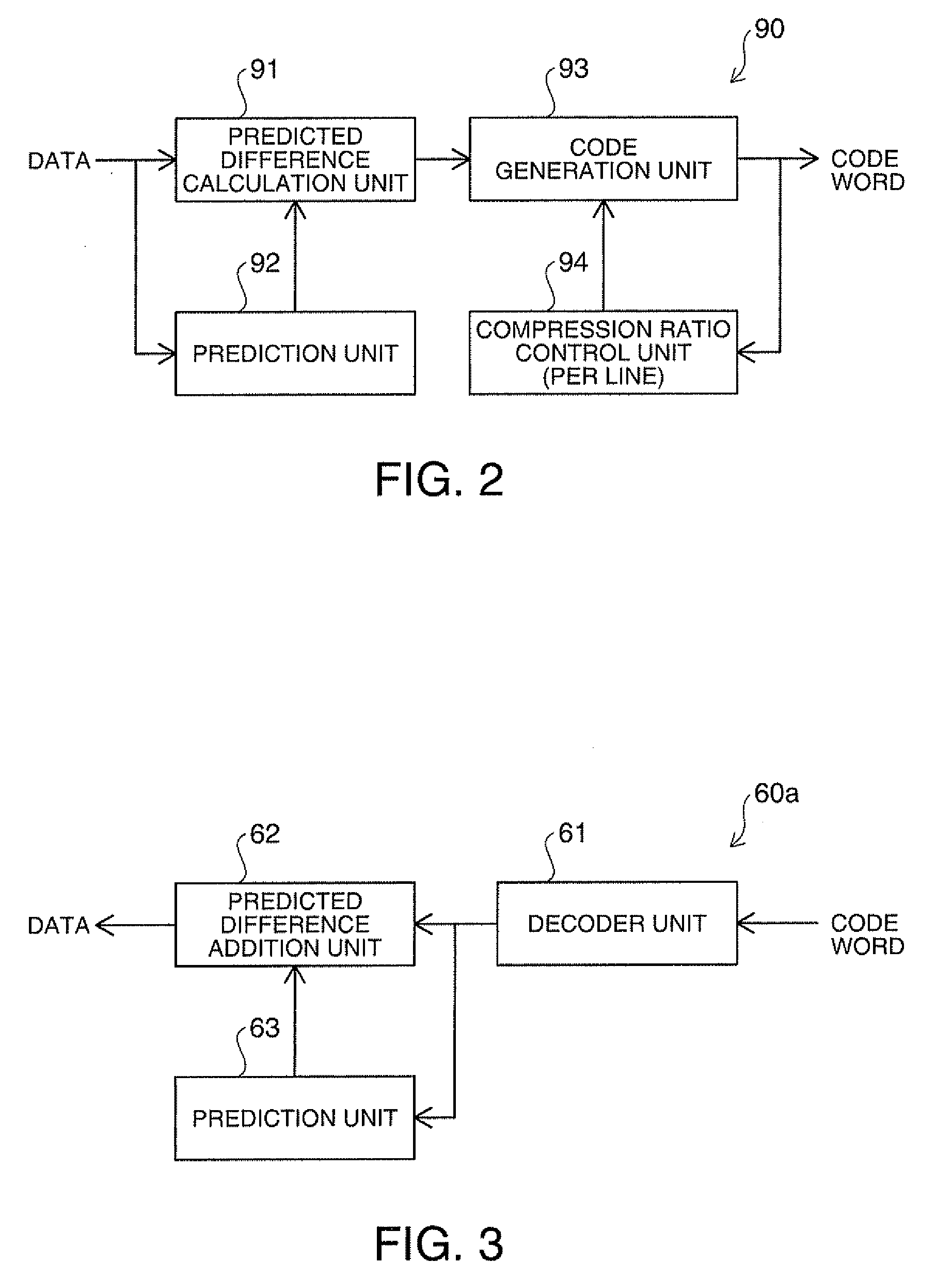
[0014]According to the image processing device having this structure, the respective sizes of the compression image data in the predetermined areas as unit of compression become fixed size. Thus, the positions storing the respective compression data on the storage medium for storing the compression data can be easily specified at the time of cutting or combining the compression image data.
[0018]According to the image processing device having this structure, the first predetermined area and the second predetermined area are the same area. Thus, the structure of the device can be simplified.

Problems solved by technology

Thus, the process requires extremely complicated operation and long time.
This problem arises not only from the DPCM method but also from various types of compression technology employed for image processing devices.

Method used


Image

  • Image processing device and image processing method
  • Image processing device and image processing method
  • Image processing device and image processing method

Examples


modified example 1

C-1. Modified Example 1

[0059]According to the embodiment described above, the image transfer circuit 50 has the source data expansion unit 60a and the destination data expansion unit 60b as two expansion units to separately expand the compressed raster data Rs and the compressed raster data Rd. However, the compressed raster data Rs and the compressed raster data Rd may be expanded by a single expansion unit. For example, only the source data expansion unit 60a is provided as the expansion unit to switch between the area judgment unit 74 and the layer unit 80 using a switch for selection of the destination of output from the source data expansion unit 60a according to data inputted to the source data expansion unit 60a.

modified example 2

C-2. Modified Example 2

[0060]According to the embodiment, the encoder unit 90 compresses data for each raster as unit in frames such that each size of compression data of raster can be equalized to easily specify each storage position of the compression raster data in the frame memory 40. However, the compression size is not limited to this structure, but may be varied for each raster. For example, data may be compressed to have the maximum compression ratio by using loss-less compression system for each raster. In this case, the memory control unit 30 produces a table showing correspondence between respective compression raster data and positions in the frame memory 40 for storing the compression raster data and stores the table in the hard disk drive 25 or the like to specify the storage position of each compression raster data corresponding to the predetermined range of the expansion image with reference to the table.

modified example 3

C-3. Modified Example 3

[0061]According to the embodiment, the predetermined area as a unit of compression corresponds to raster in frame. However, in addition to this structure, two raster or three raster may be defined as a unit of the predetermined area. The predetermined area is not limited to raster unit but may be various types of area such as block area having predetermined size.


PUM


Abstract

An image processing device includes: a first expansion unit which expands a part of first compression image data in a first predetermined area compressed as unit of compression to produce first expansion part data; a second expansion unit which expands a part of second compression image data in a second predetermined area compressed as unit of compression to produce second expansion part data; a cutting unit which cuts data in a predetermined range from the first expansion part data; a first producing unit which produces third expansion part data based on the cut data in the predetermined range and the second expansion part data; and a second producing unit which combines the second compression image data and compressed part data produced by compressing the third expansion part data in the second predetermined area as unit of compression to produce third compression image data.

Description

BACKGROUND[0001]1. Technical Field[0002]The present invention relates to an image processing technology, and more particularly to an image processing technology performed using a plurality of compression image data.[0003]2. Related Art[0004]Recently, reduction of use volume of memory included in an image processing device has been demanded with increase in image quality of images to be processed or for other reason. For example, U.S. Pat. No. 6,115,507 discloses an image processing technology which performs DPCM (differential pulse code modulation) encoding for inputted images, stores compression image data in local memory, and decodes the data in the local memory at the time of data output so as to reduce use volume of memory (see JP-A-2003-84738 as well).[0005]According to the technology shown in U.S. Pat. No. 6,115,507, however, all compression data in a source frame is decoded from the top of the data to extract necessary data at the time of writing a part of a compressed frame ...

Claims


Application Information

Patent Timeline
Patent Type & Authority Applications(United States)
IPC IPC(8): G06K9/36
CPCH04N19/115H04N19/50
Inventor TODOROKI, AKINARI
Owner COLUMBIA PEAK VENTURES LLC
Learn More