Detecting method and detecting circuit
a detection method and circuit technology, applied in the field of detection methods and detecting circuits, can solve problems such as inability to efficiently detect predetermined signals
- Summary
- Abstract
- Description
- Claims
- Application Information
AI Technical Summary
Benefits of technology
Problems solved by technology
Method used
Image

Examples
first embodiment
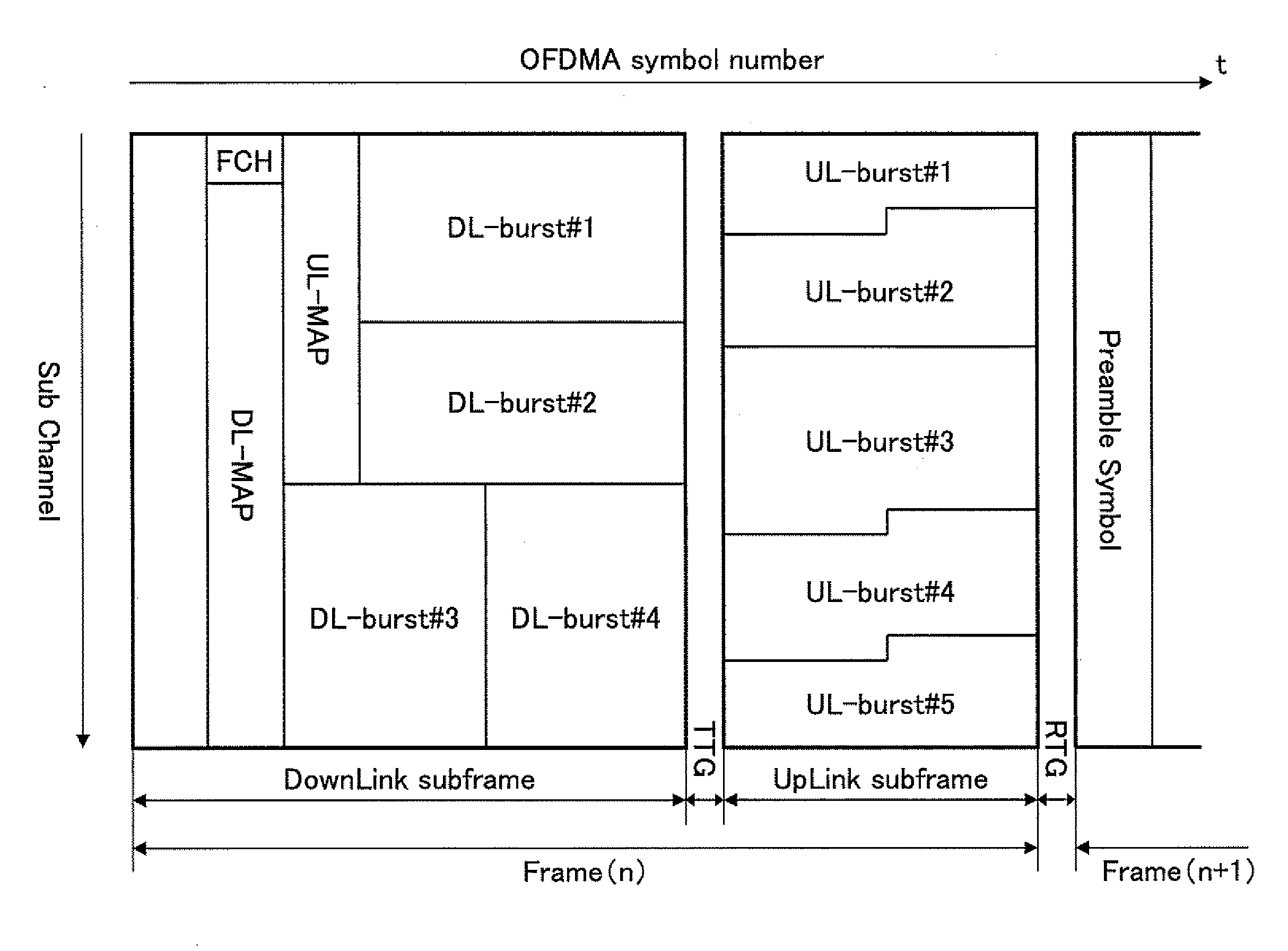
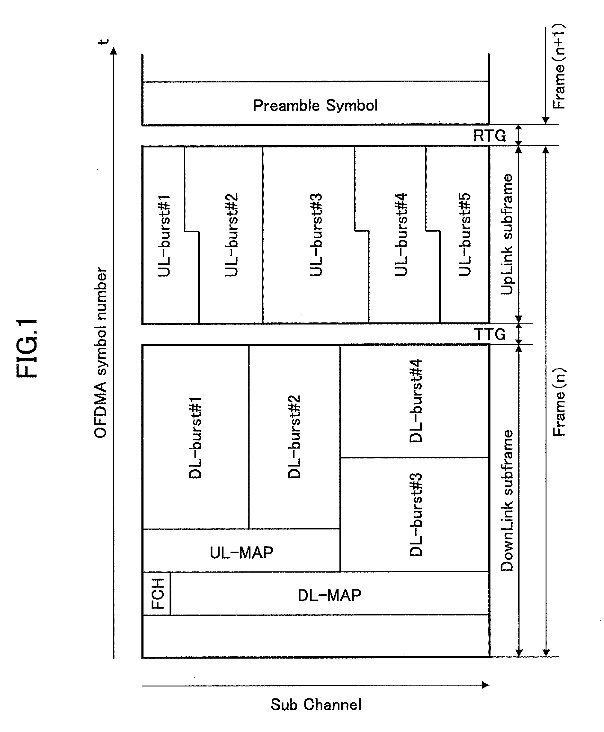
[0044]In FIG. 4, a detecting circuit 100 according to a first embodiment of the present invention receives reception signals I, Q configured as OFDM signals. The reception signals I and Q are stored in a symbol memory 41 including a dual port having a capacity capable of storing reception signals of a single symbol period (1 symbol period). The reception signal is a signal obtained by performing IFFT (Inverse Fast Fourier Transform) on the frame configuration illustrated in FIG. 1. The reception signals I, Q are also supplied to a symbol synchronization circuit (symbol synchronization part) 42. The symbol synchronization circuit 42 is configured to detect a start of a valid symbol of an OFDM signal (i.e. symbol synchronization position) and supply a symbol synchronization signal to memory control circuits 43, 44 when detecting the symbol synchronization position.
[0045]After the reception signals of a single symbol period are recorded (stored) in the symbol memory 41, the memory cont...
second embodiment
[0059]FIG. 8 illustrates a circuit configuration of a detecting circuit 200 according to a second embodiment of the present invention. FIG. 9 is a signal timing chart for describing an operation of the detecting circuit 200 of FIG. 8. In FIG. 8, like components are indicated with reference numerals similar to those of FIG. 4.
[0060]In FIG. 8, reception signals I, Q are stored in a symbol memory 61 having a capacity capable of storing reception signals of half a symbol period (1 / 2 symbol period). The reception signals I, Q are also supplied to the symbol synchronization circuit 42. Further, the reception signals are supplied to a correlation calculating part 65 in the form of reception signals I0, Q0. The symbol synchronization circuit 42 is configured to detect the start of a valid symbol of an OFDM signal (i.e. symbol synchronization position) and supply a symbol synchronization signal to a writing-purpose memory control circuit 63 and a reading-purpose memory control circuit 64 whe...
third embodiment
[0066]FIG. 10 illustrates a circuit configuration of a detecting circuit 300 according to a third embodiment of the present invention. FIG. 11 is a signal timing chart for describing an operation of the detecting circuit 300 of FIG. 10. In FIG. 10, like components are described with like reference numerals as of FIG. 4.
[0067]In FIG. 10, reception signals I, Q are stored in a symbol memory 71 having a capacity capable of storing reception signals of a single symbol period (1 symbol period). The reception signals I, Q are also supplied to the symbol synchronization circuit 42. The symbol synchronization circuit 42 is configured to detect a start of a valid symbol of an OFDM signal (i.e. symbol synchronization position) and supply a symbol synchronization signal to a memory control circuit 73 including port A and a memory control circuit 74 including port B when detecting the symbol synchronization position.
[0068]Since the memory control circuit 73 can determine the start of a valid sy...
PUM
 Abstract
Description
Claims
Application Information
 - R&D
- Intellectual Property
- Life Sciences
- Materials
- Tech Scout
- Unparalleled Data Quality
- Higher Quality Content
- 60% Fewer Hallucinations
Browse by: Latest US Patents, China's latest patents, Technical Efficacy Thesaurus, Application Domain, Technology Topic, Popular Technical Reports.
© 2025 PatSnap. All rights reserved.Legal|Privacy policy|Modern Slavery Act Transparency Statement|Sitemap|About US| Contact US: help@patsnap.com