Light-sensitive driving circuit, light-sensitive method and display

a driving circuit and light-sensitive technology, applied in the direction of lighting devices, light sources, instruments, etc., can solve the problems of increasing the threshold voltage vth, jeopardizing the current driving ability of thin film transistors, etc., to prolong the lifespan of light-sensitive apparatuses and avoid stress effects

Inactive Publication Date: 2009-09-10
WINTEK CORP
View PDF2 Cites 8 Cited by
  • Summary
  • Abstract
  • Description
  • Claims
  • Application Information

AI Technical Summary

Benefits of technology

[0007]The invention is directed to a light-sensitive driving circuit, a light-sensitive driving method and a display. The light-sensitive driving circuit outputs a pulse width modulation voltage to drive the light-sensitive apparatus, so as to avoid the stress effect, which occurs when a light-sensitive apparatus is driven by a fixed voltage, and prolong the lifespan of the light-sensitive apparatus.

Problems solved by technology

If the thin film transistor of the light-sensitive apparatus is conducted over a long duration, I-V curve drift will occur, and this is called stress effect, which increases the threshold voltage Vth of the thin film transistor and jeopardizes the current driving ability of the thin film transistor.

Method used


Image

  • Light-sensitive driving circuit, light-sensitive method and display
  • Light-sensitive driving circuit, light-sensitive method and display
  • Light-sensitive driving circuit, light-sensitive method and display

Examples


first embodiment

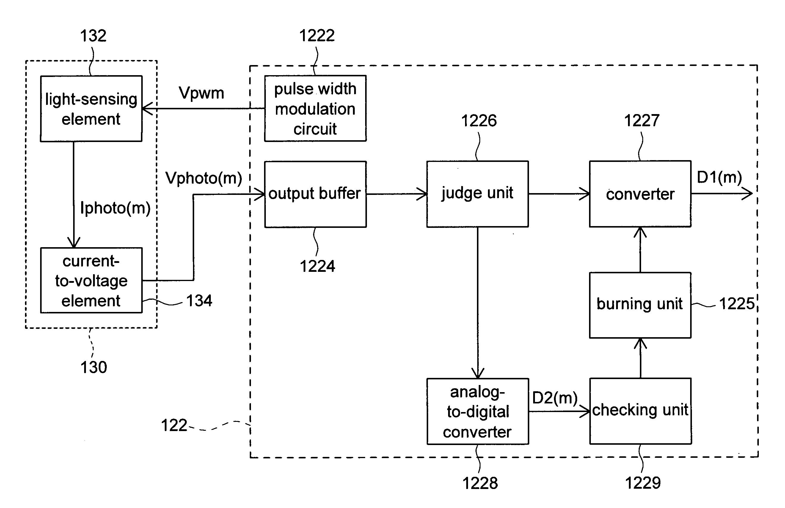
[0025]Referring to FIG. 4, a light-sensitive apparatus and a light-sensitive driving circuit according to a first embodiment of the invention is shown. The light-sensitive driving circuit 122 and the light-sensitive apparatus 130 can be implemented in many ways. In the first embodiment, the light-sensitive 5 apparatus 130 comprises a light-sensing element 132 and a current-to-voltage element 134. The light-sensitive driving circuit 122 comprises a pulse width modulation (PWM) circuit 1222, an output buffer 1224, a burning unit 1225, a judge unit 1226, an analog-to-digital converter 1227, an analog-to-digital converter 1228 and a checking unit 1229.

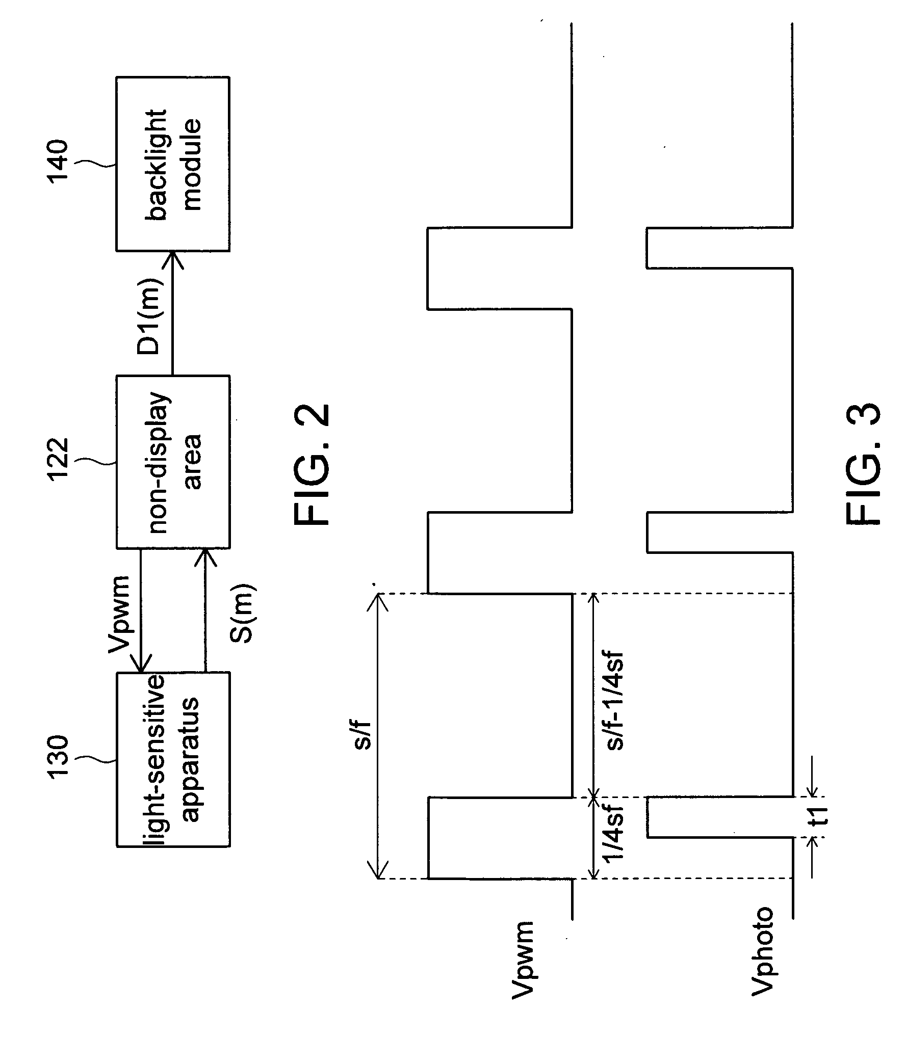
[0026]When the induced signal S(m) of FIG. 2 is an induced voltage, the pulse width modulation circuit 1222 provides a pulse width modulation voltage Vpwm to drive light-sensing element 132 of the light-sensitive apparatus 130, so that the surrounding luminance m of the external light of the light-sensing element 132 outputs a correspondin...

second embodiment

[0034]Referring to FIG. 5, a light-sensitive apparatus and a light-sensitive driving circuit according to a second embodiment of the invention is shown. The light-sensitive driving circuit 122 and the light-sensitive apparatus 130 can be implemented by way of the first embodiment or the second embodiment. In the second embodiment, the light-sensitive apparatus 130 comprises a light-sensing element 132, and the light-sensitive driving circuit 122 comprises a current-to-voltage element 134, a pulse width modulation (PWM) circuit 1222, an output buffer 1224, a burning unit 1225, a judge unit 1226, an analog-to-digital converter 1227, an analog-to-digital converter 1228 and a checking unit 1229.

[0035]When the induced signal S(m) of FIG. 2 is an induced current, the light-sensitive apparatus 130 of the second embodiment does not comprise the current-to-voltage element 134, but instead, integrates the current-to-voltage element 134 into the light-sensitive driving circuit 122. The pulse w...


PUM


Abstract

A light-sensitive driving circuit, a light-sensitive driving method and a display are provided. The light-sensitive driving circuit comprises a pulse width modulation circuit, a judge unit and a first analog-to-digital converter. The pulse width modulation circuit provides a pulse width modulation voltage to drive a light-sensitive apparatus, so that the light-sensitive apparatus outputs an induced signal according to an external light. The judge unit judges whether a check and burn procedure needs to be operated or not according to an external command. If the check and burn procedure does not need to be operated, the first analog-to-digital converter outputs a digital signal according to the induced signal.

Description

[0001]This application claims the benefit of Taiwan application Serial No. 97108403, filed Mar. 10, 2008, the subject matter of which is incorporated herein by reference.BACKGROUND OF THE INVENTION[0002]1. Field of the Invention[0003]The invention relates in general to a light-sensitive driving circuit, and more particularly to a light-sensitive driving circuit capable of prolonging the lifespan of the light-sensitive apparatus, a light-sensitive driving method and a display.[0004]2. Description of the Related Art[0005]For the backlight luminance of the display device, most conventional technologies directly apply a fixed voltage to drive the light-sensitive apparatus and adjust the backlight luminance of display device according to a signal outputted by the light-sensitive apparatus.[0006]If the thin film transistor of the light-sensitive apparatus is conducted over a long duration, I-V curve drift will occur, and this is called stress effect, which increases the threshold voltage ...

Claims


Application Information

Patent Timeline
Patent Type & Authority Applications(United States)
IPC IPC(8): G09G3/36H05B37/02
CPCG09G3/3406G09G2360/144G09G2320/0693G09G2320/064
Inventor LAI, CHIH-CHANGWANG, WEN-CHUN
Owner WINTEK CORP
Why Eureka
Try Eureka