
Method and Apparatus for Testing Tubular Objects

a technology for testing tubular objects and apparatus, applied in the direction of measuring devices, scientific instruments, instruments, etc., can solve the problems of false test results and high complexity of assembling and disassembling test apparatuses

Inactive Publication Date: 2009-09-10
CORENSO UNITED
View PDF7 Cites 10 Cited by
  • Summary
  • Abstract
  • Description
  • Claims
  • Application Information

AI Technical Summary

Benefits of technology

[0004]From DE 603 00 993 T2, a method is known, in which the tubular component to be tested is received in a cylindrical pressure chamber, whose interior diameter is much larger than the component to be tested. The intermediary cavity is filled with small balls, which are pressurized from the outside in order to impart an even pressure onto the cambered surface of the tubular component to be tested. In order to prevent a direct contact of the pressure with the balls and with the component to be tested, a rubber membrane is provided onto which the pressure is imparted and by which the pressure is imparted onto the balls, which contact the surface of the tubular component. In order to achieve a sufficient tightness, it is thus required to fill the existing pressure cavity after inserting the tubular component, and to seal the cavity, so that the imparted pressure only impacts the balls provided therein. It has thus proven to be detrimental that the complexity of assembling and disassembling the test apparatus is very high, so that only few tubular components can be tested by the same testing apparatus in adequate time.
[0042]It is provided in a particular configuration that the test apparatus comprises a shaft, which is supported by support elements, and comprises a hand wheel, wherein the sensors are rotationally connected to a shaft. By the shaft, the concentricity can be tested before or after the pressure test has been performed, which has to be considered in particular for fast running print presses.
[0043]Thus, it can be stated in summary, that through the method according to the invention and through the apparatus provided for performing the method, a plurality of tubular objects can be tested within a short period of time with respect to their pressure resistance, wherein the particularity of the method is that a quick exchange of the tubular object is assured and complex sealing measures, threaded connections, etc., which are required after each insertion of a tubular object, can be avoided. By the apparatus, furthermore a continuous test process can be performed comprising a quick exchange of the tubular objects and an immediate reuse of the test apparatus.

Problems solved by technology

Due to the high pressure, which has to be imparted, however, there are recurring problems regarding a reliable sealing, and furthermore, it cannot be ruled out that due to the direct contact with the hydraulic fluid a falsification of the test results occur.
It has thus proven to be detrimental that the complexity of assembling and disassembling the test apparatus is very high, so that only few tubular components can be tested by the same testing apparatus in adequate time.

Method used


Image

  • Method and Apparatus for Testing Tubular Objects
  • Method and Apparatus for Testing Tubular Objects
  • Method and Apparatus for Testing Tubular Objects

Examples


Embodiment Construction

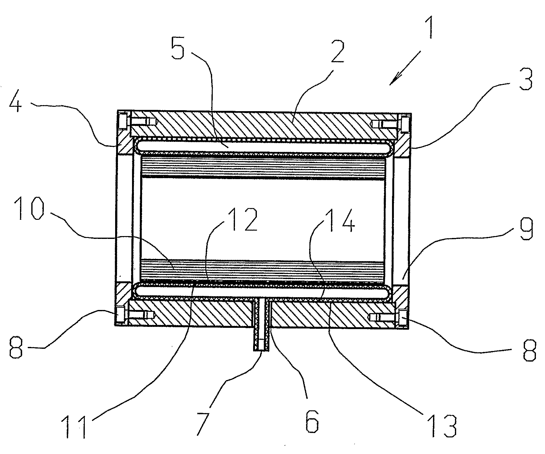
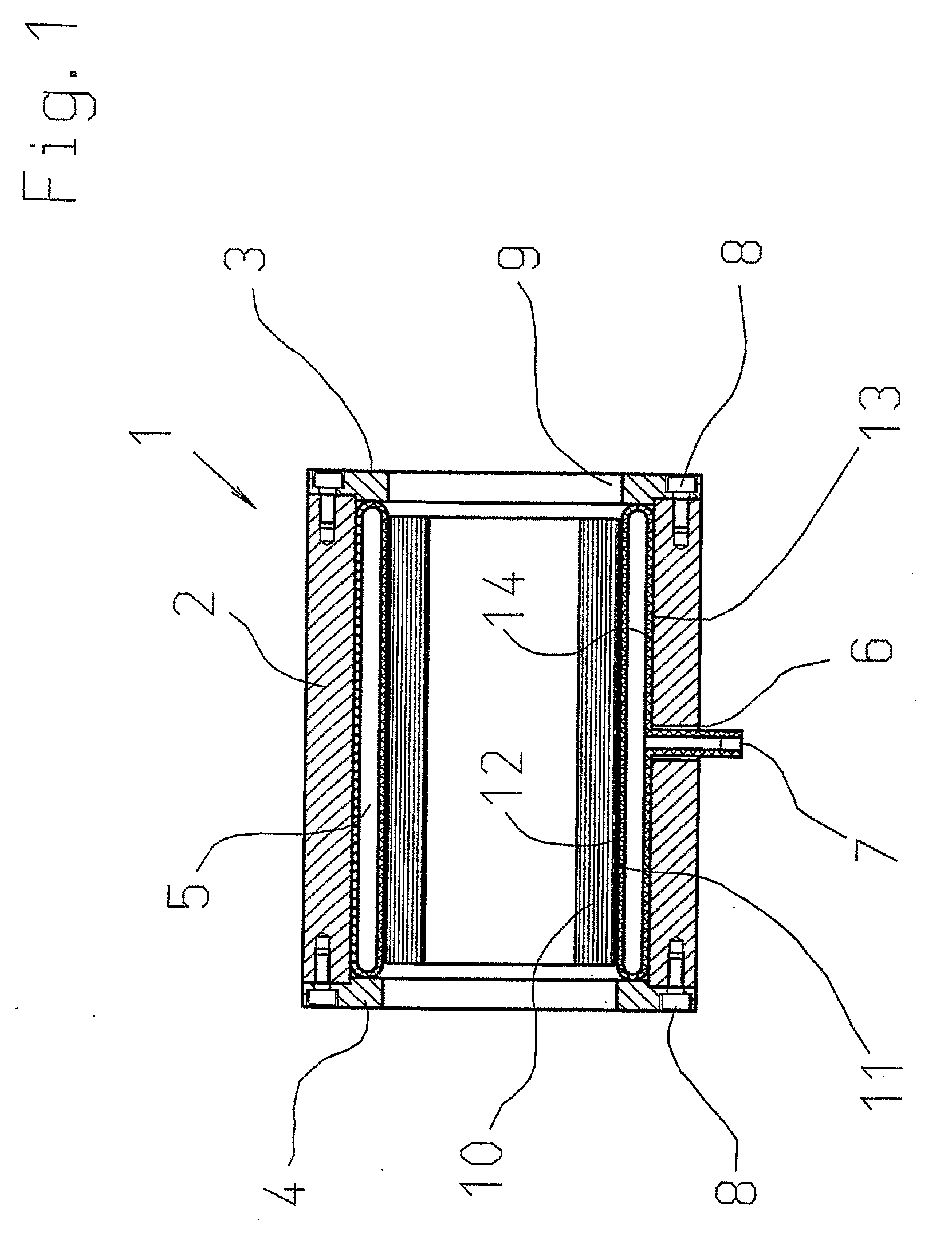
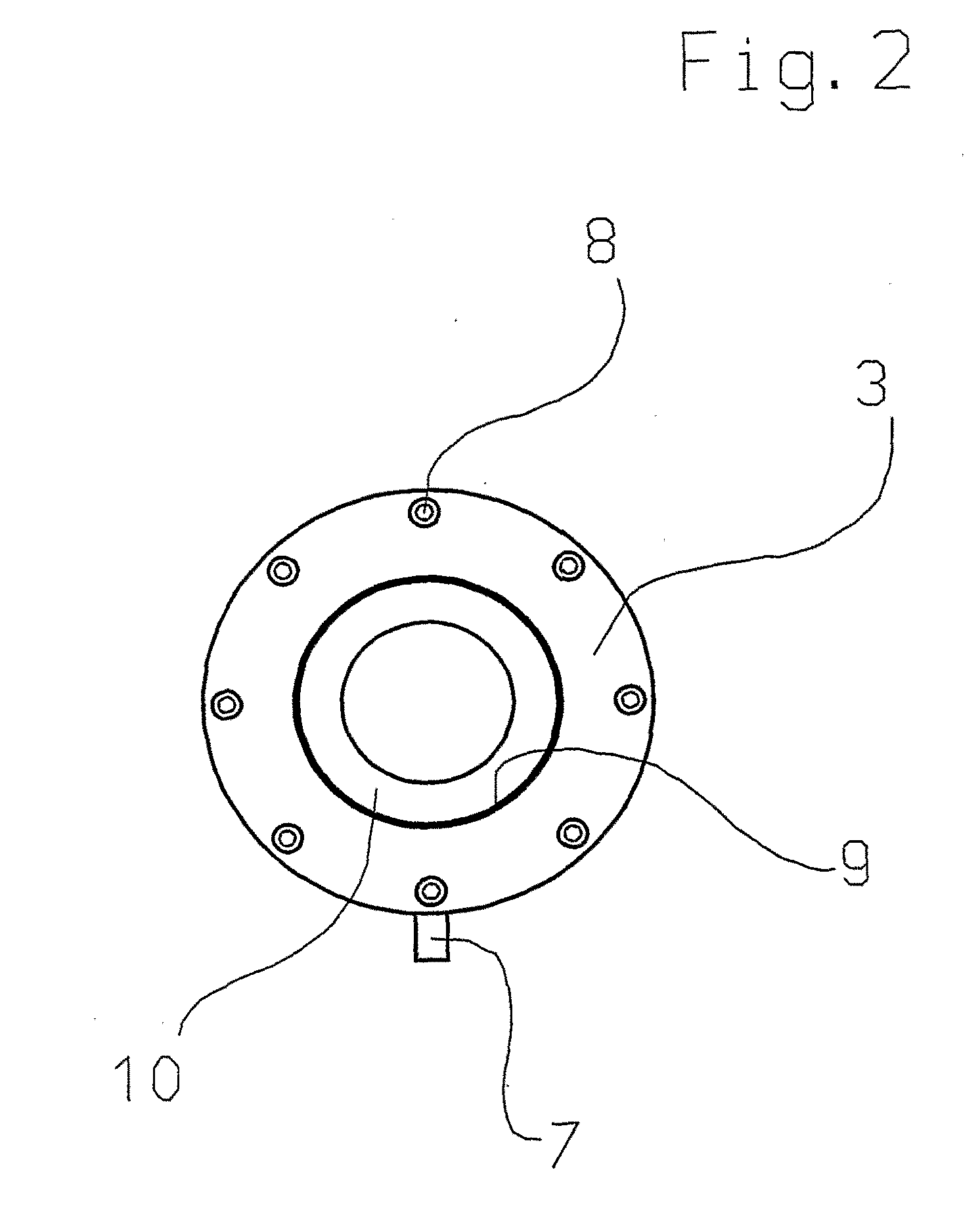
[0018]FIG. 1 shows an apparatus 1 according to the invention in a sectional side view, comprised of a hollow cylinder 2, two flange disks 3, 4 at the faces, and a pressure shell 5. The hollow cylinder 2 comprises an opening 6, through which a pressure connection 7 of the pressure shell 5 is run to the outside. At the face side, the hollow cylinder 2 is defined by two flange disks 3, 4, which are bolted to the hollow cylinder 2 by mounting bolts 8. The flange disks 3, 4 comprise an opening 9, through which the tubular object 10, which is to be tested, can be inserted.

[0019]For the intended purpose, a paper sleeve section is used as an object 10, which is inserted into the apparatus 1 over its entire length and which is in direct contact with its inner surface with the inner surface 12 of the pressure shell 5. However, it is conceivable that the apparatus 1 is also used for testing other tubular objects, e.g. plastic sleeves. The pressure shell 5 contacts the inner surface 14 of the h...


PUM

PropertyMeasurementUnit
lengthaaaaaaaaaa
pressureaaaaaaaaaa
hydraulic pressureaaaaaaaaaa

Abstract

A method for testing tubular objects, in particular paper sleeves in a cylindrical pressure chamber, comprises the following steps: receiving the tubular object to be tested in a pressure chamber, which is comprised of a hollow cylinder with a pressure shell, wherein the pressure shell is supported at the hollow cylinder and wherein an expansion of the pressure shell in radial outward direction and in axial direction is limited; loading the pressure shell with a pressure means, so that the inner surface of the pressure shell is evenly applied to the surface of the object; and providing a pressure increase until the terminal pressure to be tested is reached, or a damage of the tubular object occurs. The invention also relates to an apparatus for testing tubular objects, configured to use the method.

Description

CROSS REFERENCE TO RELATED APPLICATIONS[0001]This application is a continuation of International Application No. PCT / DE07 / 000,864, filed May 10, 2007, claiming priority of German patent application DE102006023110A1, filed May 16, 2006, the disclosures of which are incorporated herein by reference.BACKGROUND OF THE INVENTION[0002]The invention relates to a method for testing tubular objects, in particular paper sleeves, in a cylindrical pressure chamber and an apparatus to use the method.[0003]So far testing methods are known, in which the tubular objects are directly loaded by a hydraulic fluid. Due to the high pressure, which has to be imparted, however, there are recurring problems regarding a reliable sealing, and furthermore, it cannot be ruled out that due to the direct contact with the hydraulic fluid a falsification of the test results occur.[0004]From DE 603 00 993 T2, a method is known, in which the tubular component to be tested is received in a cylindrical pressure chambe...

Claims


Application Information

Patent Timeline
Patent Type & Authority Applications(United States)
IPC IPC(8): G01N3/12
CPCG01N3/12G01N33/34G01N2203/0411G01N2203/0274G01N2203/0019
Inventor SCHWAB, ANDREAS
Owner CORENSO UNITED
Learn More