
Fuel Ratio Control in a Combustion Apparatus with Multiple Fuel Supply Lines

a technology of fuel supply line and combustion apparatus, which is applied in the direction of combustion control, lighting and heating apparatus, machines/engines, etc., can solve the problems of damage to the combustor and impair its performance, and achieve the effect of reducing the risk of such overheating and affecting its performan

Active Publication Date: 2009-09-03
SIEMENS ENERGY GLOBAL GMBH & CO KG
View PDF1 Cites 22 Cited by
  • Summary
  • Abstract
  • Description
  • Claims
  • Application Information

AI Technical Summary

Benefits of technology

The invention is about a combustion apparatus that reduces the risk of overheating and damage to the combustor. It does this by monitoring various parameters, such as temperature and pressure, and adjusting the fuel supplies to the burners accordingly. This allows the apparatus to maintain the temperature of the protected parts below a predetermined limit while still maintaining optimal performance. The invention can be used in gas turbine engines, boilers, and other combustion apparatus.

Problems solved by technology

It is a common problem that, due to the high temperatures generated inside such combustors, various component parts of the combustors run the risk of overheating, which can seriously damage the combustor, or at least impair its performance.

Method used


Image

  • Fuel Ratio Control in a Combustion Apparatus with Multiple Fuel Supply Lines
  • Fuel Ratio Control in a Combustion Apparatus with Multiple Fuel Supply Lines
  • Fuel Ratio Control in a Combustion Apparatus with Multiple Fuel Supply Lines

Examples


Embodiment Construction

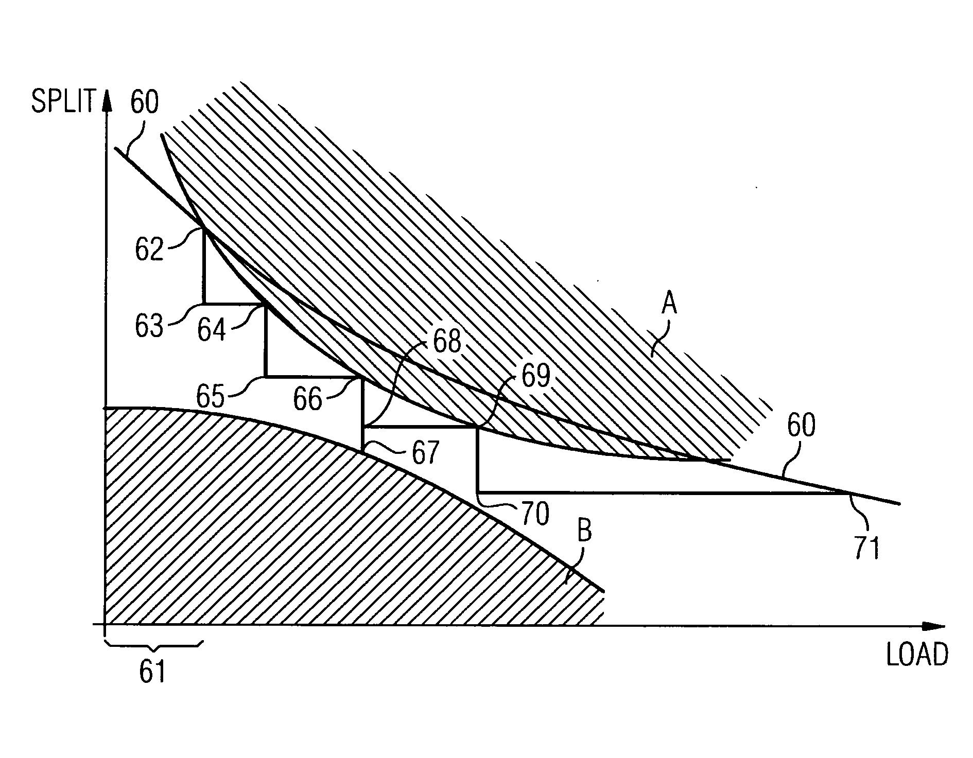
[0039]The present inventors have recognised that it is possible to prevent over-heating of a component part of a combustion apparatus due to the combustion process in the combustion area by varying the main / pilot fuel supplies to the combustor without varying the overall fuel supply to the apparatus. It is normally desirable to maintain a constant total fuel supply to a combustor (or set of combustors, where there is more than one) in order to match a constant load imposed on the apparatus, which may be, for example, a gas turbine. Where the load on the gas turbine changes, it will then be necessary to change the total fuel supply to the gas turbine, but not otherwise, normally.

[0040]The concept behind the present invention is illustrated in FIG. 4, which is a graph of load versus main / pilot fuel split. In the graph the hatched area shown as A represents a set of operating conditions in which a component part of a combustor is in danger of suffering damage due to overheating. Hence ...


PUM


Abstract

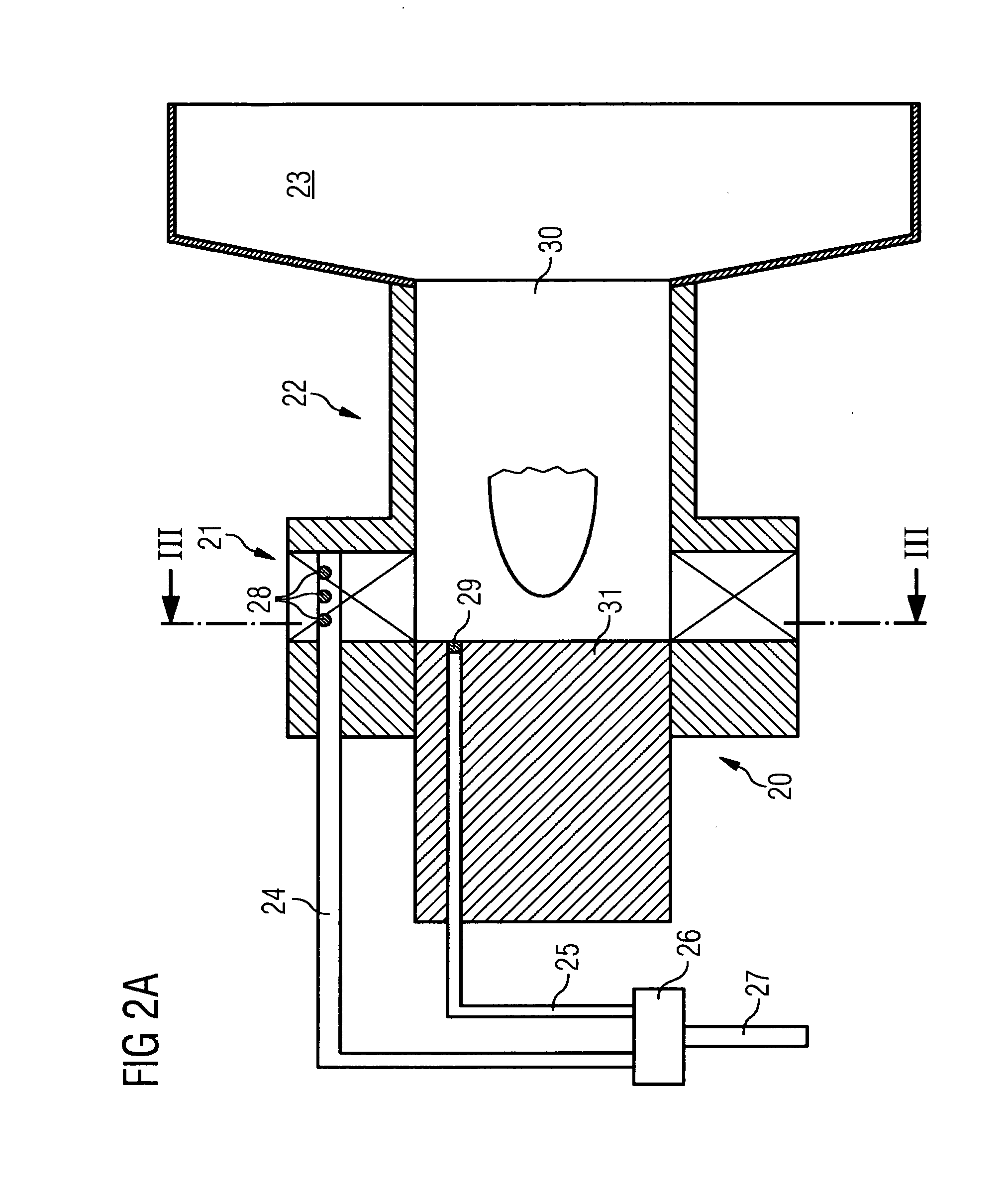
A combustion apparatus is provided which includes an incoming fuel supply line that supplies fuel in a plurality of fuel-supply lines to one or more burners, the burners being associated with a combustion volume. A temperature sensor is located in the apparatus so as to yield temperature information relating to a component part of the apparatus, which is to be prevented from overheating The apparatus also includes a control arrangement, which detects the temperature-sensor output and, depending on that output, varies the fuel supplies to one or more of the burners in such a way as to maintain the temperature of the component part below a maximum value, while keeping the fuel in the incoming fuel supply line substantially constant. The control unit preferably also strives to adjust the operating conditions of the apparatus so that pressure oscillations are kept below a maximum value.

Description

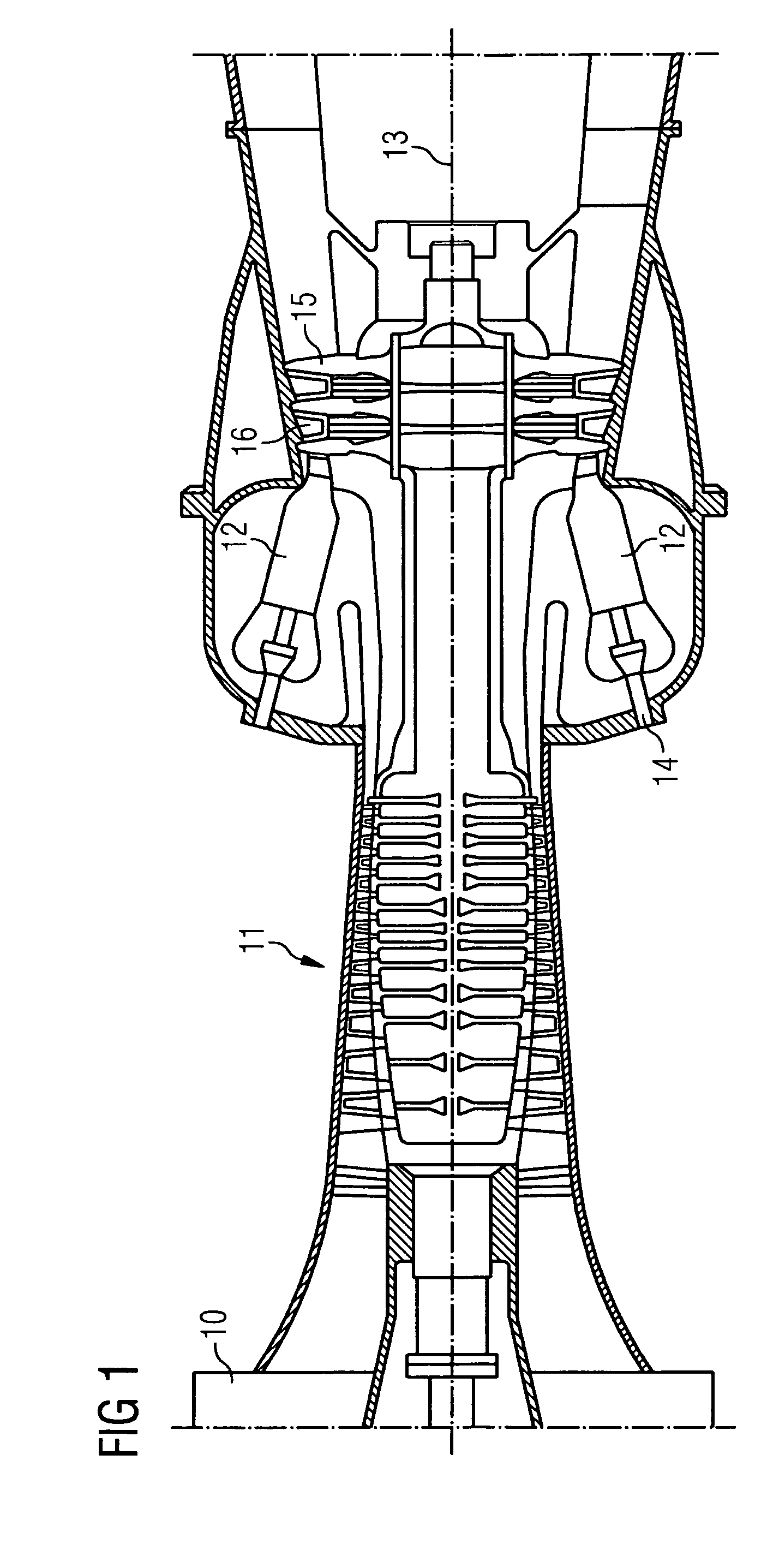
CROSS REFERENCE TO RELATED APPLICATIONS[0001]This application is the US National Stage of International Application No. PCT / EP2006 / 069494, filed Dec. 8, 2006 and claims the benefit thereof. The International Application claims the benefits of United Kingdom application No. 0601038.3 GB filed Jan. 19, 2006, both of the applications are incorporated by reference herein in their entirety.FIELD OF INVENTION[0002]The invention relates to a combustion apparatus and to a combustion apparatus constituted in particular by a gas turbine.BACKGROUND OF INVENTION[0003]Combustion apparatus is employed in a number of different environments, including gas turbines, furnaces and boilers.[0004]An example of a typical gas-turbine arrangement is shown in FIG. 1. The gas turbine comprises an air inlet 10 at one end followed by a compressor stage 11 in which incoming air is compressed for application to one or more combustors 12, which are distributed circumferentially around the turbine axis 13. Fuel is...

Claims


Application Information

Patent Timeline
Patent Type & Authority Applications(United States)
IPC IPC(8): F02C9/26F02C7/22F23N5/24
CPCF02C7/228F02C9/34F23D2900/14701F23N5/02F23N5/242F05D2270/3032F23R3/34F23R3/46F23R2900/00013F05D2270/112F23N2037/02F23N2237/02F02C9/28
Inventor BULAT, GHENADIEMCMILLAN, ROBIN
Owner SIEMENS ENERGY GLOBAL GMBH & CO KG
Learn More