
Photovoltaic ladder inverter

a photovoltaic ladder and inverter technology, applied in the direction of dc-ac conversion without reversal, dc-ac circuit constant-current supply, transportation and packaging, etc., can solve the problem of uninterruptible power supply, conventional dc-to-ac inverter design, and high-speed switching process may generate undesired harmonic frequencies

Inactive Publication Date: 2009-08-27
STELLARIS
View PDF7 Cites 24 Cited by
  • Summary
  • Abstract
  • Description
  • Claims
  • Application Information

AI Technical Summary

Benefits of technology

"The present invention provides a solar inverter device that can connect to an electrical power grid. It includes a photovoltaic module stack with capacitors for storing output, and a positive and negative termination circuit for switching the negative end of the module stack to ground during half cycles of the grid. The device also has a common bus with connecting branches that selectively couple the output of the PV modules. A current control device is connected to the common bus, and each branch includes a positive and negative cycle switch controlled by a corresponding drive circuit. The device can maintain a constant current through the switches and detect the half cycles of the grid to switch the appropriate termination circuit. The technical effects of the invention include improved efficiency and reliability of solar energy utilization, as well as simplified and flexible installation."

Problems solved by technology

Such devices include, for example, solar inverters, variable frequency drives, and uninterruptible power supplies.
In any such cases, there are a number problems associated with conventional DC-to-AC inverter designs.
For instance, the high-speed switching process may generate undesired harmonic frequencies.
In addition, conventional inverter technologies are typically expensive and may contain complicated electronic circuits and many components, further increasing cost.
Such high cost can be of particular concern in solar photovoltaic applications, as the cost of the inverters may represent a significant percentage of the overall photovoltaic system cost.

Method used


Image

  • Photovoltaic ladder inverter
  • Photovoltaic ladder inverter
  • Photovoltaic ladder inverter

Examples


Embodiment Construction

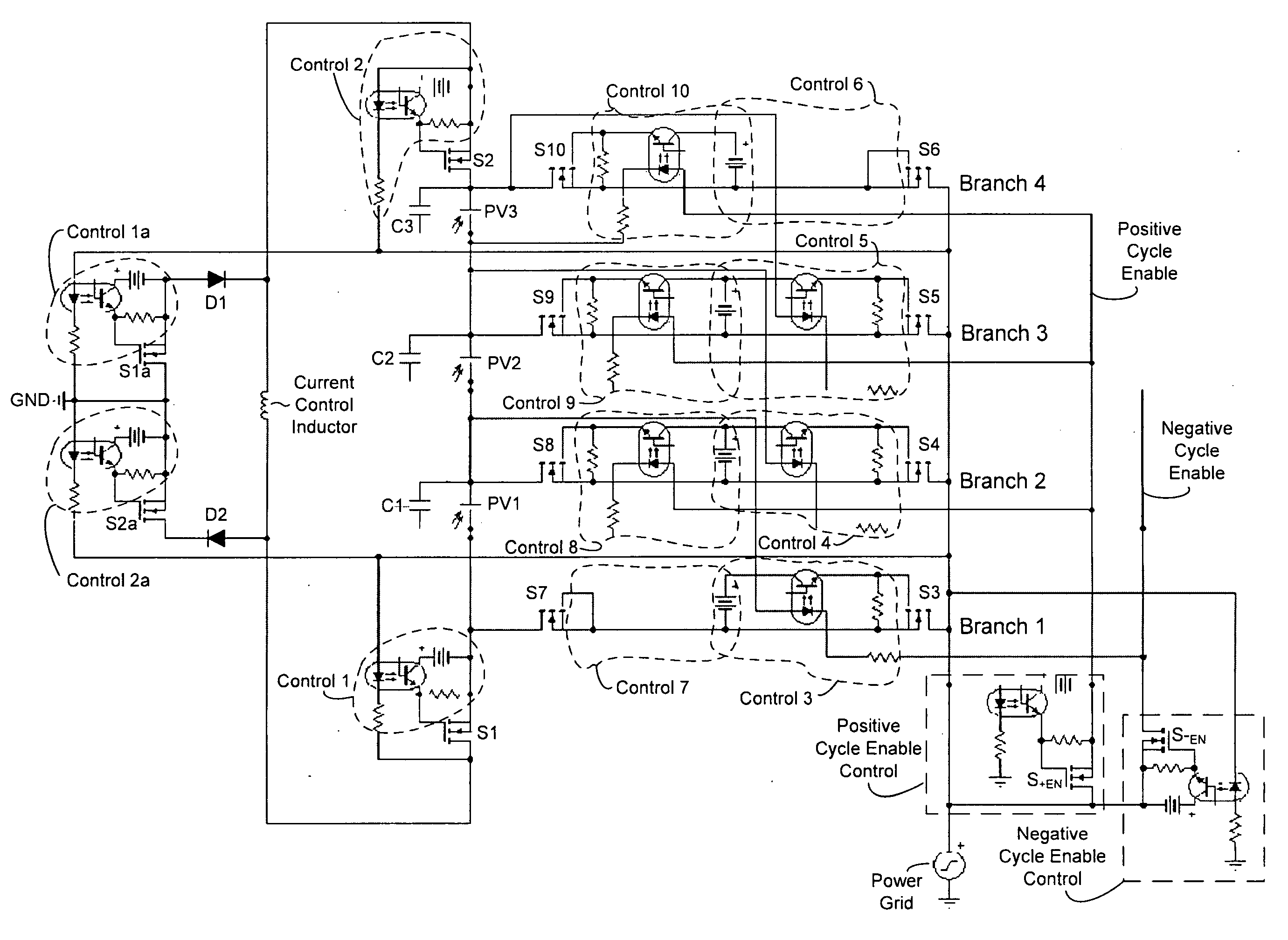
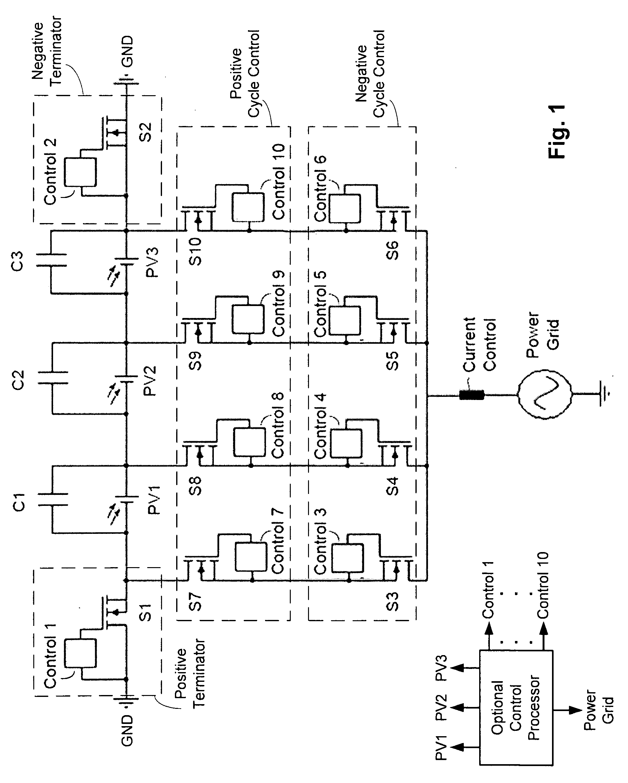
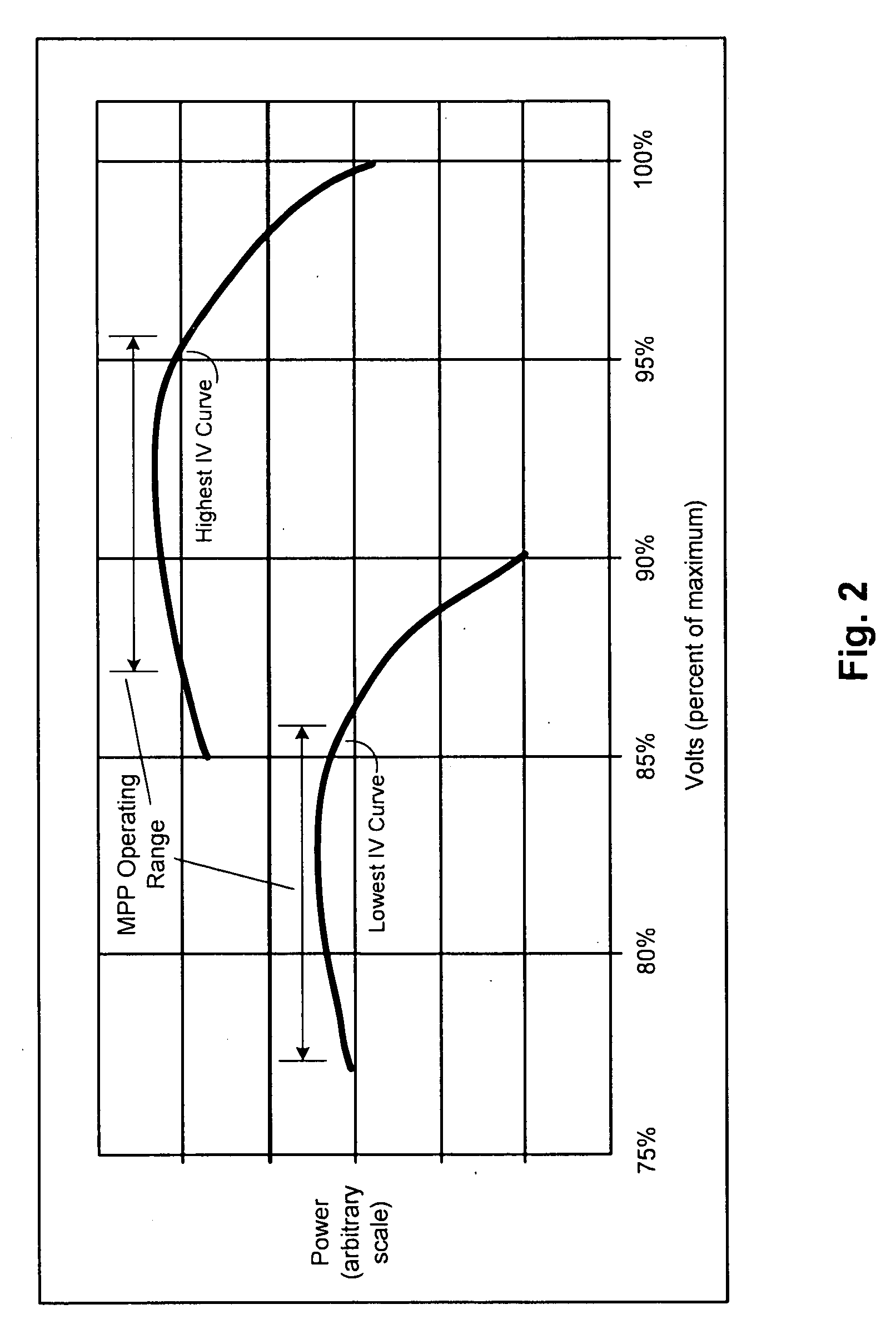
[0017]Techniques are disclosed that allow for efficient DC-to-AC conversion. The techniques may be implemented, for example, in a DC-to-AC inverter device that is relatively less expensive, includes significantly fewer components, and / or reduces or otherwise eliminates harmonics, relative to conventional DC-to-AC inverter designs. The techniques may be employed in any number of applications, such as in a system for converting discrete a DC source from a plurality of batteries or photovoltaic cells (or other suitable DC source) into a relatively smooth AC voltage output that may be used by AC devices and / or provided to an electric power grid. The system may be further configured to vary the output voltage from the inversion process to, for instance, ensure adequate voltage for the target application, or to allow for optimizing the output of a photovoltaic array to ensure maximum power point tracking.

[0018]Photovoltaic Ladder

[0019]FIG. 1 illustrates a circuit diagram of a solar invert...


PUM


Abstract

Techniques for DC-to-AC conversion are disclosed, and may be embodied in a solar inverter device that can operatively couple to a power grid. The device includes a photovoltaic (PV) stack including series-connected PV modules. Each PV module is associated with a capacitor for storing output of that PV module. A positive terminator circuit switches a negative end of the PV stack to ground during positive half of grid cycle, and a negative terminator switches a positive end of the PV stack to ground during negative half of grid cycle. A connecting branch couples each PV module output to a common bus, each branch including control circuitry configured to selectively couple the corresponding PV module output to bus. During a first half of grid cycle, some of the capacitors discharge to the grid while a balance of the capacitors charge in preparation for discharge during a second half of grid cycle.

Description

RELATED APPLICATIONS[0001]This application claims the benefit of U.S. Provisional Application No. 61 / 030,424, filed on Feb. 21, 2008, which is herein incorporated by reference in its entirety.FIELD OF THE INVENTION[0002]The invention relates to power conversion, and more particularly, to techniques for DC-to-AC conversion in solar applications.BACKGROUND OF THE INVENTION[0003]There are many electronic devices that require or otherwise employ the conversion of DC electricity to AC electricity, typically by operation of an inverter. Such devices include, for example, solar inverters, variable frequency drives, and uninterruptible power supplies.[0004]Solar inverters may be used, for instance, to convert the DC output of solar photovoltaic modules to an AC output that can be utilized by AC devices, or provided to an electric power grid. Uninterruptible power supplies typically use batteries to provide a DC source, which is then inverted to produce an AC output. Variable frequency drive...

Claims


Application Information

Patent Timeline
Patent Type & Authority Applications(United States)
IPC IPC(8): H02J1/04
CPCH02M7/48H02J3/383Y02E10/563H02J2300/24H02J3/381Y02E10/56H02J3/46
Inventor PAULL, JAMES B.
Owner STELLARIS
Learn More