Fluted hopper tee
- Summary
- Abstract
- Description
- Claims
- Application Information
AI Technical Summary
Benefits of technology
Problems solved by technology
Method used
Image
Examples
Embodiment Construction
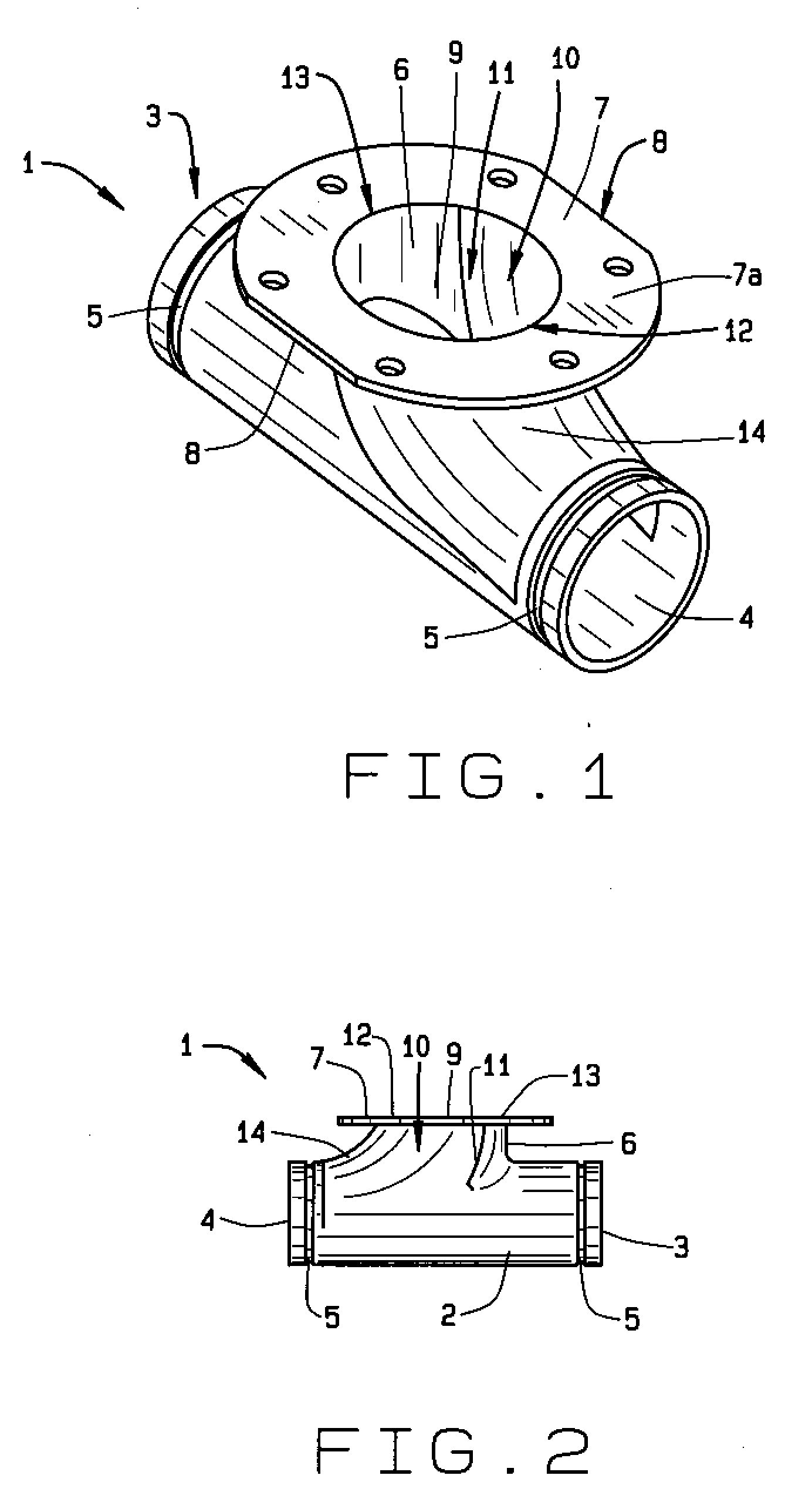
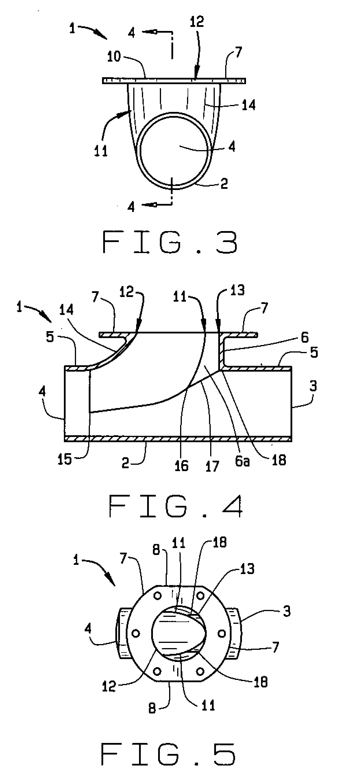
[0054]In referring to the drawings, FIG. 1 shows an integral tee, generally known as a hopper tee, of the present invention 1 in a perspective view. The present invention has a generally transverse hollow pipe, hereinafter horizontal pipe 2, round in cross section and of a known diameter. The horizontal pipe has two opposed ends, one end being an inlet 3 that receives material sent into the hopper tee under pneumatic pressures and the opposite end being an outlet 4 that discharges material from the inlet and material unloaded from a hopper, or bin, into the hopper tee. The inlet and the outlet each have a perimeter slot 5 for coupling the invention 1 into a pneumatic system for unloading. The coupling slots 5 generally extend around the entire circumference of the lower pipe proximate the inlet and the outlet.
[0055]Generally centered upon and perpendicular to the horizontal pipe, the fluted hopper tee 1 has a vertically directed hollow pipe, hereinafter vertical pipe 6. The horizont...
PUM
 Abstract
Description
Claims
Application Information
 - R&D
- Intellectual Property
- Life Sciences
- Materials
- Tech Scout
- Unparalleled Data Quality
- Higher Quality Content
- 60% Fewer Hallucinations
Browse by: Latest US Patents, China's latest patents, Technical Efficacy Thesaurus, Application Domain, Technology Topic, Popular Technical Reports.
© 2025 PatSnap. All rights reserved.Legal|Privacy policy|Modern Slavery Act Transparency Statement|Sitemap|About US| Contact US: help@patsnap.com


