
Hose clamp removal and installation tool

a technology of installation tool and hose clamp, which is applied in the direction of metal-working hand tools, metal-working wire tools, metal-working apparatus, etc., can solve the problems that the design of such tools may not provide desired benefits or advantages, and achieve the effect of facilitating the positioning of tangs or ends, preventing slippage of the band hose clamp, and facilitating the alignment of the hose clamp

Inactive Publication Date: 2009-08-13
LISLE CORPORATION
View PDF6 Cites 7 Cited by
  • Summary
  • Abstract
  • Description
  • Claims
  • Application Information

AI Technical Summary

Benefits of technology

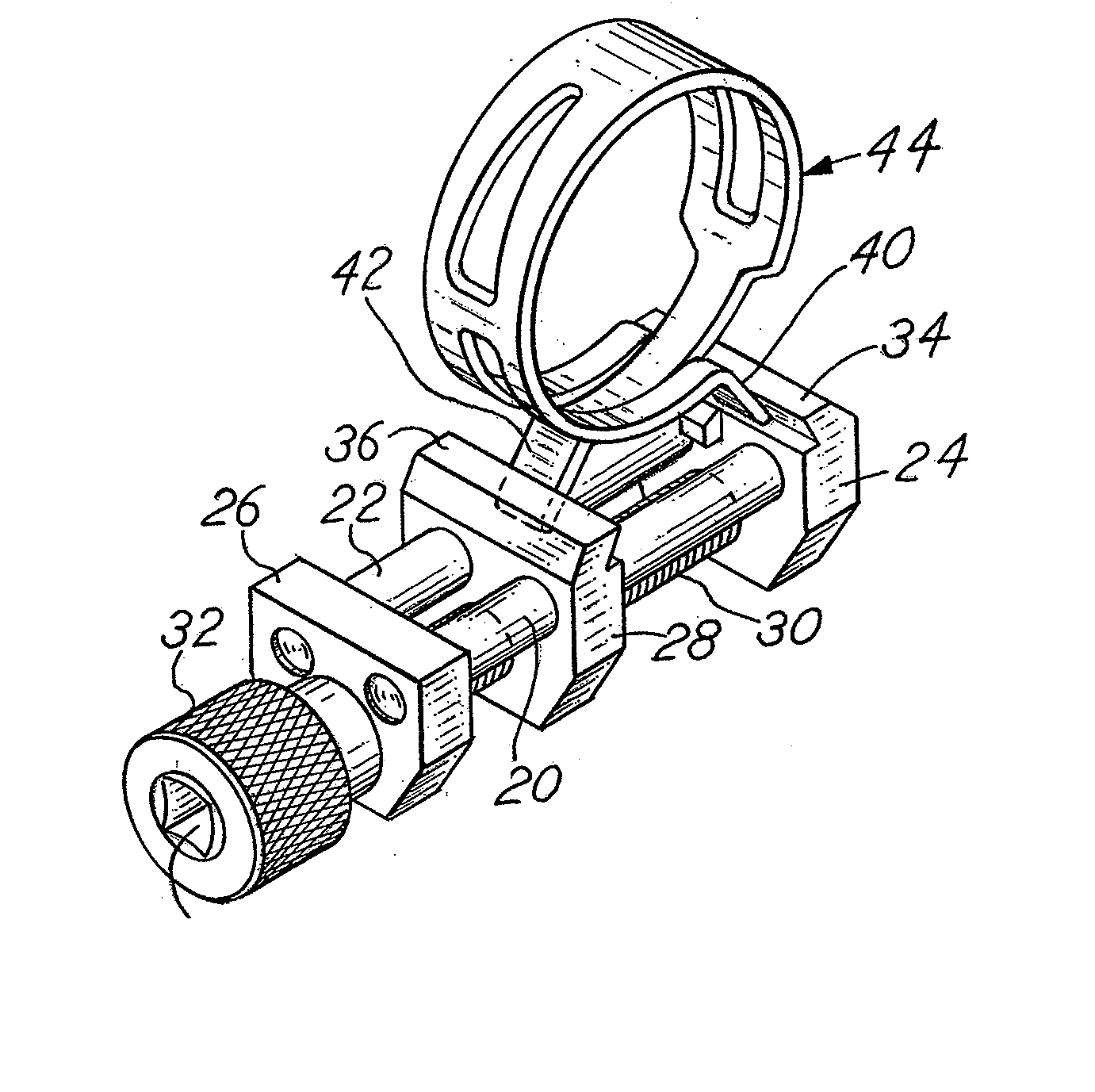
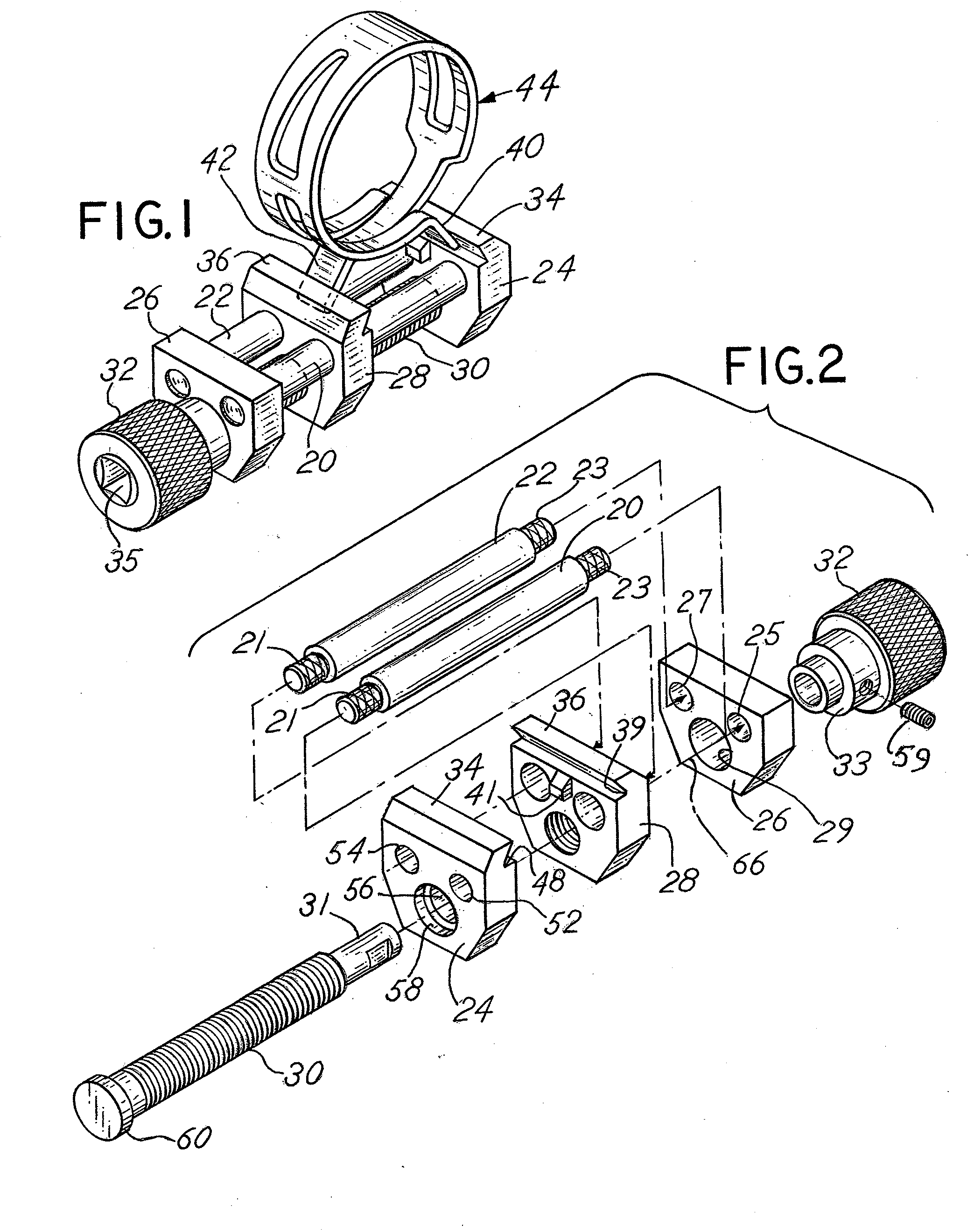
[0008]The hose clamp removal tool includes first and second cylindrical parallel rails connected together by opposed, spaced end plates. An intermediate slide plate is slidably mounted on the rails between the first and second, spaced end plates that are affixed to the parallel rails. The slide plate is threadably engaged by a threaded rod, that is, journaled at opposite ends in the first and second end plates and thus is slidably movable between the first and second end plates upon rotation of the threaded rod. The slide plate and opposed first end plate each include a tang engagement member which, in a disclosed embodiment, comprises a transverse slot and a guide ramp which facilitates positioning of the tangs or ends of a hose clamp within the clamp device between the slide plate and a fixed end plate. Additionally, the slide plate and opposed first end plate each include at least one off center slot or channel extending normal to the transverse slot in the respective plates, each slot sized to engage circular cross section tangs of circular cross section or wire hose clamps.
[0009]The rails of the hose clamp are spaced laterally, one from the other, in a manner which facilitates alignment of a band type hose clamp appropriately between the rails. The rails function to preclude slippage of the band hose clamp from the hose clamp tool during operation of the tool. The band hose clamp tool may thereby be engaged with the tangs of a hose clamp to thereby effectively open or spread the hose clamp. The tool may remain engaged with the band style hose clamp and facilitate replacement of the band hose clamp on a hose once a repair or replacement operation has been effected.
[0010]The ring or wire type hose clamp is maintained against slippage by the slots in the opposed end plate and slide plate. The slots in the end plate and slide plate are equidistant from the center line axis between the parallel rails to avoid skewing of the clamp upon removal.
[0012]It is a further object of the invention to provide a hose clamp tool which facilitates maintenance of a hose clamp in engagement with the hose clamp tool for band type and ring or wire type hose clamps.
[0014]Another object of the invention is to provide a hose clamp tool which is rugged, easy to use, compact, capable of being made in various sizes, useful in restricted spaces, capable of use in combination with a socket type drive, and generally inexpensive.

Problems solved by technology

While such tools provide some functionality which achieves the objective of engaging and holding a hose clamp in an open position, the design of such tools may not provide desired benefits or advantages.

Method used


Image

  • Hose clamp removal and installation tool
  • Hose clamp removal and installation tool
  • Hose clamp removal and installation tool

Examples


first embodiment

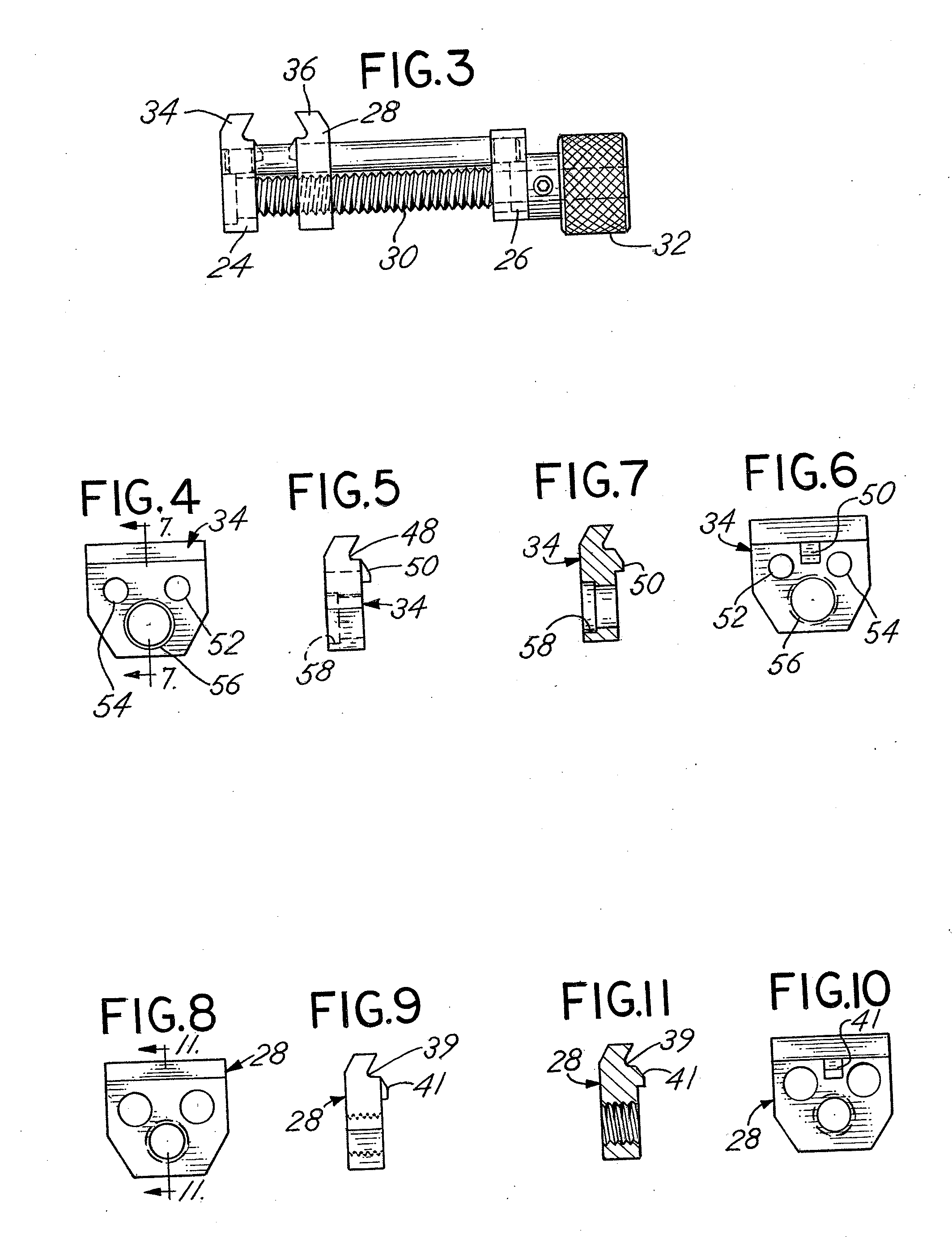
[0051]Referring to FIGS. 1-17, the hose clamp tool of the invention is comprised of a multiple number of component parts which are assembled as described herein. Those parts are depicted in an exploded isometric view (FIG. 2) and can be summarized as follows. The tool includes first and second, parallel generally cylindrical rails 20 and 22. The first and second rails 20, 22 are designed to connect a fixed, spaced first plate 24 to a second or parallel base plate 26 which is also affixed to and spaced from the first or fixed plate 24. A parallel sliding plate 28 is slidably mounted on the first and second rails 20 and 22 and is threadably engaged by a rotatable, threaded rod 30 journaled through first plate 24 and second or base plate 26. Rod 30 is situated beneath rails 20, 22 with engagement elements or opposed jaws 34, 36 on opposed jaws 24, 28, respectively, situated above and along the upper side of the rails 20, 22. Rod 30 may be rotated by means of attached knob 32 to move th...

second embodiment

[0065]Alternatively, a band type wire clamp, such as illustrated in FIG. 1, may still be utilized and compressed using the second embodiment compression tool inasmuch as the cross channels such as the channels 39 and 48 are maintained in the embodiment of FIGS. 18-34. As a consequence, the construction of the embodiment of FIGS. 18-34 is useful with both a band type hose clamp as well as a wire type hose clamp and may be used in a manner which provides for avoidance of torqueing or twisting the hose clamp as it is removed regardless of the type of the clamp that is being used. The channels 102 and 104, of course, may be sized so as to be cooperative with multiple sizes or gauge of wire associated with a wire or ring type clamp 144. Each channel 102, 104 subtends or generally bottoms against a surface, such as the surface 110, of the slot 39 subtending the channel 104, and the surface 112 of the slot 48 subtending the channel 102. The surfaces 112 and 110 comprise a means for limitin...


PUM

PropertyMeasurementUnit
circumferenceaaaaaaaaaa
distanceaaaaaaaaaa
diameteraaaaaaaaaa

Abstract

A hose clamp compression tool for engaging and compressing opposed or opposite end tangs of a hose clamp includes a first fixed plate and jaw and a second fixed plate spaced from the first fixed plate and jaw. The first and second plates are mounted on rails with a sliding plate and jaw also mounted on the rails and positioned between the fixed plates. The sliding plate is rotatably adjustable in spacing from the one fixed plate by means of a threaded rod journaled to the fixed plates and threaded to the sliding plate. The jaws each include both a transverse slot cooperative with an end tang of a band type hose clamp and a channel extending from the slot for engagement with the end tang of a ring or wire type hose clamp thereby enabling use of the tool for either a band type or a wire type hose clamp.

Description

CROSS REFERENCE TO RELATED APPLICATION[0001]This is a continuation-in-part application incorporating by reference and claiming priority to previously filed co-pending utility application Ser. No. 11 / 509,943 filed Aug. 25, 2006 entitled “Hose Clamp Removal and Installation Tool” and provisional application Ser. No. 60 / 596,316 filed Sep. 15, 2005 entitled “Spring Band Clamp Removal Tool”.BACKGROUND OF THE INVENTION[0002]In a principal aspect, the present invention relates to a tool for installation and / or removal of a hose clamp type in the form of a generally circular band or wire ring with at least first and second projecting end tangs that may be engaged to move toward one another and thereby expand the circumference of the band to release the band from a hose or other clamping operation performed by the band.[0003]Hose clamps are often utilized in the automotive field and for numerous other purposes to retain a hose inserted or fitted onto a tubular shaft, hose fitting or stem. A ...

Claims


Application Information

Patent Timeline
Patent Type & Authority Applications(United States)
IPC IPC(8): B25B27/10
CPCB25B1/103Y10T29/53613Y10T29/5363B25B25/005
Inventor THAYER, RICHARD D.
Owner LISLE CORPORATION
Learn More