
Non-contact ultrasound materials systems and measurement techniques

a non-contact, material technology, applied in the direction of instruments, heat measurement, specific gravity measurement, etc., can solve the problem that the conventional ultrasonic coupling mode cannot be effectively applied to materials

Active Publication Date: 2009-08-13
THE ULTRAN GRP INC
View PDF7 Cites 7 Cited by
  • Summary
  • Abstract
  • Description
  • Claims
  • Application Information

AI Technical Summary

Benefits of technology

[0007]According to a preferred embodiment, a specimen is supported between the first and second planes by an x-y positioning stage controlled by the controller enabling the generation of two-dimensional profiles of the speed through the specimen.

Problems solved by technology

Conventional ultrasonic coupling modes cannot be effectively applied to materials such as consolidated particles (green ceramics, powder metals, pharmaceutical tablets and other like materials), porous, early stage formation of polymers, and other materials that are sensitive to liquid couplants or any contact.

Method used


Image

  • Non-contact ultrasound materials systems and measurement techniques
  • Non-contact ultrasound materials systems and measurement techniques
  • Non-contact ultrasound materials systems and measurement techniques

Examples


Embodiment Construction

Technique #1

Determination of Material Ultrasound Velocity by Automatic Measurement of its Thickness and Ultrasound Time-of-Flight (TOF) Through it

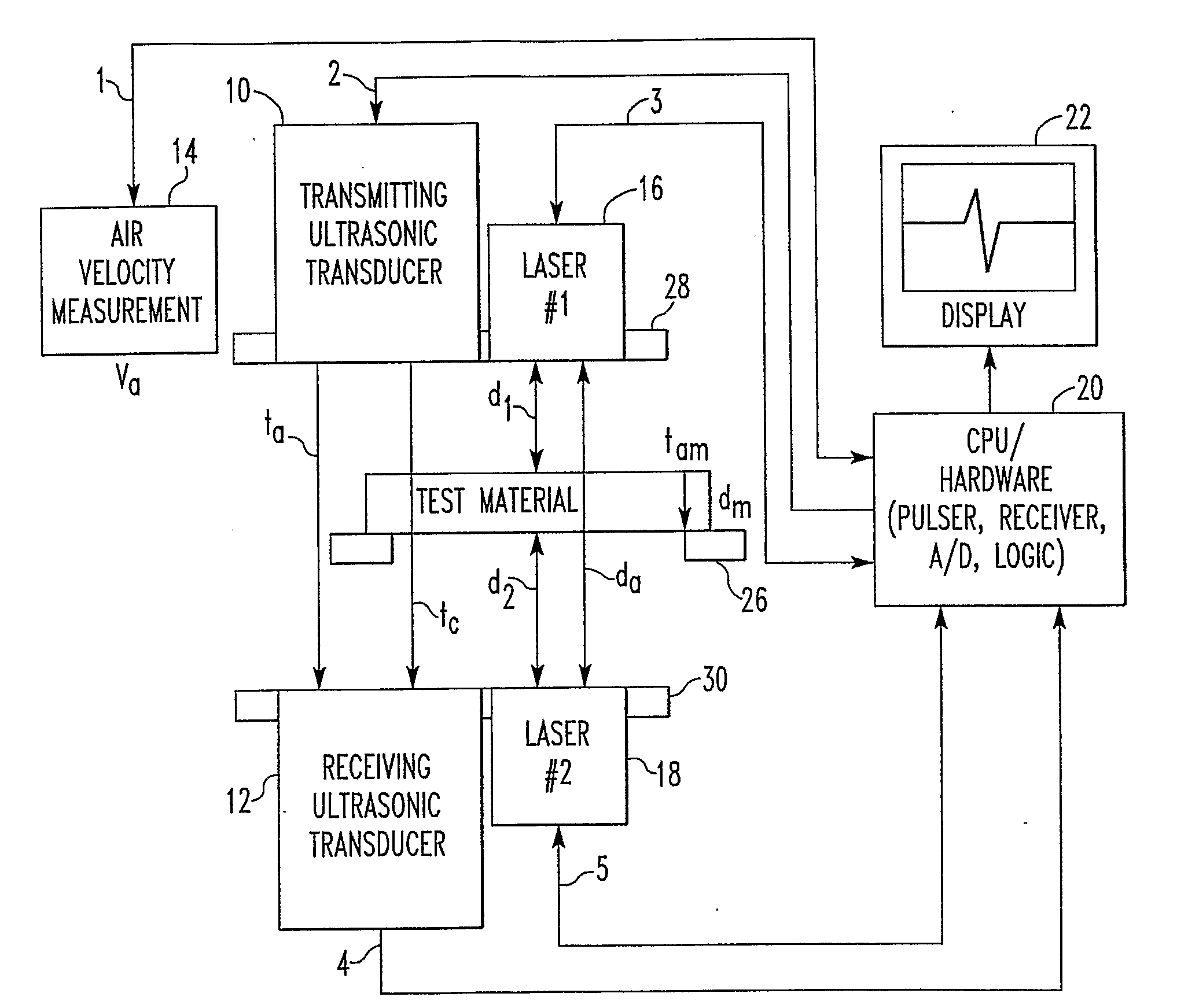
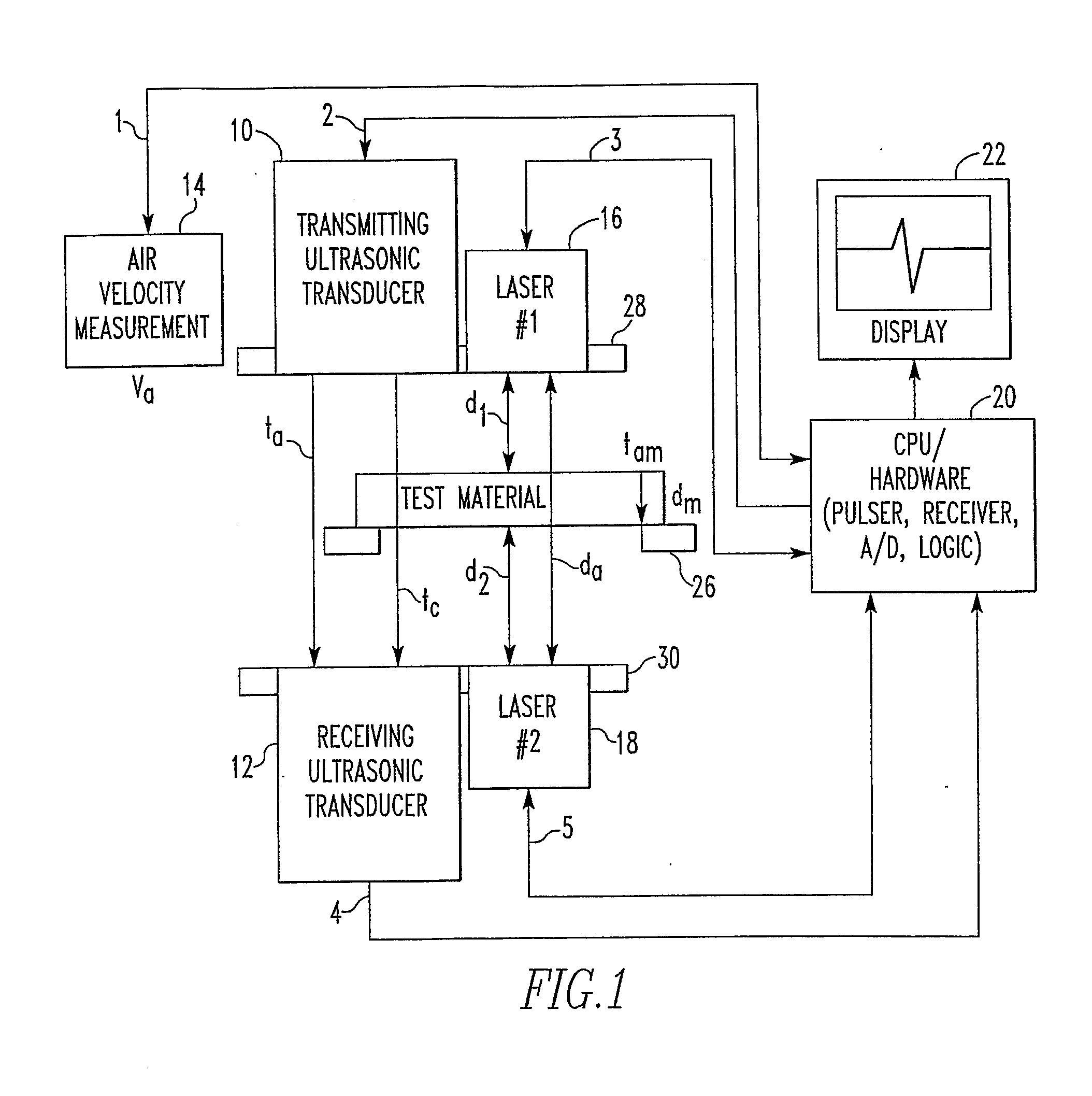
[0015]A schematic shown in FIG. 1 depicts hardware for this technique, which includes: a transmitting and receiving pair of ultrasonic transducers 10, 12, an additional ultrasonic transducer 14 operating in pulse-echo mode, a pair of laser distance sensors, and controller 20 and display 22. A support 28 holds the transmitting ultrasound transducer and one laser distance sensor in a first plane. A support 30 holds the receiving ultrasound transducer and the other laser distance sensor in a second plane. A support 26 is provided for positioning the specimen between the first and second planes. The controller may be provided with internally integrated or an external transmitting transducer excitation mechanism, such as a pulser, receiving transducer amplification mechanism, such as a receiver amplifier, analog-to-digital converter, and logic ...


PUM


Abstract

Apparatus for determining the speed of sound through a specimen comprises an ultrasound sending transducer, an ultrasound receiving transducer, a pair of laser distance sensors, a display device, a controller in communication with the ultrasound sending transducer, the ultrasound receiving transducer and the pair of laser distance sensors and the display device. The ultrasound sending transducer and one laser distance sensor are supported with a transducer surface in a first plane. The ultrasound receiving transducer and one last distance sensor are supported with a transducer surface in a second plane parallel with the first plane. A support for a specimen is provided between the first and second planes. The controller is programmed for gathering data from the ultrasound transducers and the laser distance sensors for calculating the speed of ultrasound in the specimen and displaying the results.

Description

BACKGROUND OF THE INVENTION[0001]The use of ultrasound for determination of physical properties, texture, and microstructure is well known. Specifically, it is also well known that ultrasound velocity of a material is directly proportional to its density and porosity. However, in order to determine ultrasound velocity in materials (material velocity) or other properties, the conventional ultrasound mode involves either direct or indirect contact of a transducer to the test material. For example, in order to efficiently transmit ultrasound in the test material, the transducer is physically coupled to the material by liquid couplants, dry contact couplants, or by submerging the material in liquids, generally water. Conventional ultrasonic coupling modes cannot be effectively applied to materials such as consolidated particles (green ceramics, powder metals, pharmaceutical tablets and other like materials), porous, early stage formation of polymers, and other materials that are sensiti...

Claims


Application Information

Patent Timeline
IPC IPC(8): G01N29/07
CPCG01H5/00
Inventor BHARDWAJ, MAHESH C.EISCHEID, THOMAS J.BIVIANO, MICHAEL S.SRIVATSA, RAGHU S.BHARDWAJ, NEERAJ S.
Owner THE ULTRAN GRP INC
Learn More