
Stepped pin assembly for an axle and method therefor

a technology of stepped pins and axles, applied in the direction of screws, washing machines, ways, etc., can solve problems such as excessive play

Inactive Publication Date: 2009-08-13
SVENSKA EXPANDER
View PDF8 Cites 16 Cited by
  • Summary
  • Abstract
  • Description
  • Claims
  • Application Information

AI Technical Summary

Benefits of technology

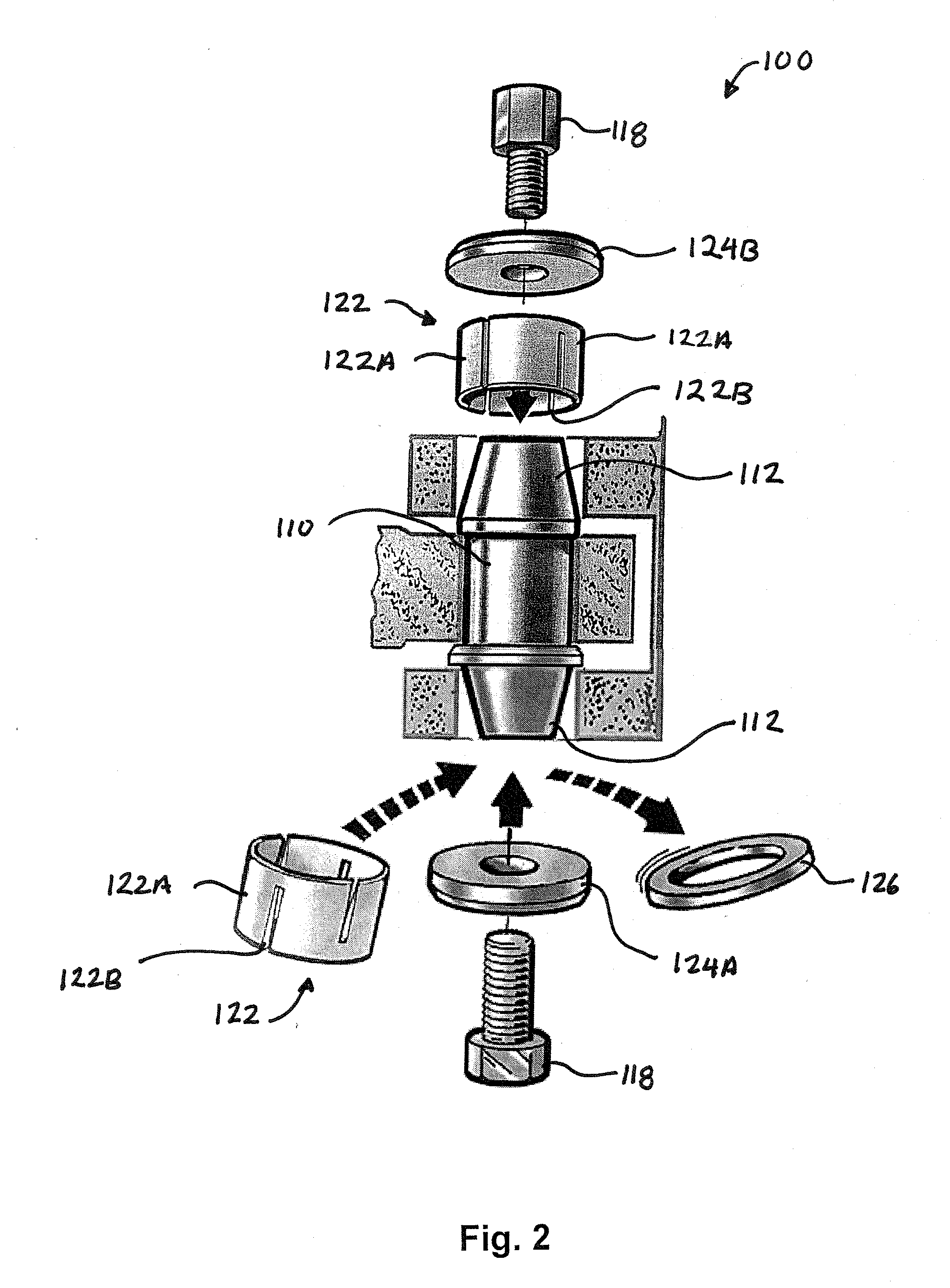
[0005]A method of installing a pin assembly for providing a stable anchor on multiple ends comprises: providing a pin assembly comprising: an axle having a first and second end members formed on the axle; a bearing mounted on a central section of the axle; a spacer; a pair of expansion sleeves, wherein one of the pair of expansion sleeves is positioned over each of the end members of the axle; and a pair of locking devices; positioning the spacer between the bearing and one of the first or second mounting ends; positioning the axle so that the axle is placed in a first opening in a first mounting end of a component part and extends to a second opening in a second mounting end of the component part, the axle passing through the bearing and the spacer element and through the second opening; attaching one of the pair of fastening element to the second end member to eliminate axial play; placing one of the pair of expansion sleeves over the first end member of the axle; and attaching a second of the pair of fastening elements to the first end member and tightening so that the one of the pair of expansion sleeves expands and press against an interior wall of the first opening.

Problems solved by technology

Since relative movement between the inner bearing race and the axle produces progressively increasing wear resulting in excessive play and perhaps fracture of the axle, the race has to be fixed relative to the axle by means of nuts screwed onto the respective axle ends.
It is important that the nuts are tightened just the right amount, since excessive tightening may jeopardize the attachment of the mounting cheeks, and excessive play may arise as a result of insufficient tightening, with the results mentioned above

Method used


Image

  • Stepped pin assembly for an axle and method therefor
  • Stepped pin assembly for an axle and method therefor
  • Stepped pin assembly for an axle and method therefor

Examples


Embodiment Construction

[0011]The present invention provides an arrangement for an axle for a bearing-mounted hinge for which a very stable fixing of the inner race of the bearing can be obtained. Referring to FIGS. 1 and 2, a stepped pin assembly 100 is shown. The stepped pin assembly 100 is used to pivotally couple two component parts 102 and 104 of a machine together. In the embodiment shown in FIGS. 1 and 2, the stepped pin assembly 100 is positioned between two mounting cheeks 106 of the component part 102. A spacer element 108 is generally positioned between the lower component part 104 and the mounting cheeks 106.

[0012]The pin assembly 102 will have an axle 110. A pair of end members 112 is formed on each end of the axle 110. In the embodiment shown in FIGS. 1 and 2, the end members 112 are tapered so that the distal end of the end members 112 is narrower than the proximal end. However, this is just shown as an example. The end members may be cylindrical in shape as will be discussed below.

[0013]The...


PUM

PropertyMeasurementUnit
Lengthaaaaaaaaaa
Shapeaaaaaaaaaa

Abstract

A pin assembly for providing a stable anchor on multiple ends has an axle having a pair of end members formed on each end of the axle. The axle is placed in a first opening in a first mounting end of a component part and extends to a second opening in a second mounting end of the component part. A bearing is mounted on a central section of the axle. A spacer is positioned between the bearing and one of the first or second mounting ends. A pair of expansion sleeves is provided wherein one of the pair of expansion sleeves is positioned over each of the end members of the axle. A pair of locking devices is provided wherein one of the pair of locking devices is coupled to each of the end members. When tightened, the locking devices cause the expansion sleeves to press against interior walls of the first and second openings to anchor the axle.

Description

FIELD OF THE INVENTION[0001]This invention relates generally to an arrangement for an axle which is anchored at two points situated at the ends of the axle and, more specifically, to an arrangement for an axle for a bearing-mounted hinge by means of which very stable fixing of the inner race of the bearing can be obtained.BACKGROUND OF THE INVENTION[0002]The conventional way to achieve pivotability in a connection between two machine parts is to use a hinge journalled in bearings, comprising one or more bearings arranged on an axle which is fixed in between a pair of mounting cheeks or the like on one of the machine parts. The inner race of the bearing or bearings is disposed on the axle and, possibly with the aid of distancing rings, bridges the distance between the fixing cheeks, while the outer race of the bearing or bearings is effectively connected to the second machine part. Since relative movement between the inner bearing race and the axle produces progressively increasing w...

Claims


Application Information

Patent Timeline
IPC IPC(8): E05D5/12E05D5/10F16B13/06F16B35/00F16B37/00F16B43/00B21K13/02
CPCE05D5/12E05D5/121F16B2/14Y10T29/24F16C11/045Y10T16/557F16B9/023
Inventor SVENSSON, ROGERCARLSSON, ANDERSSVENSSON, EVERTH
Owner SVENSKA EXPANDER
Learn More