Cylinder injection type spark ignition internal combustion engine

a fuel injection and internal combustion engine technology, applied in the direction of machines/engines, electrical control, mechanical equipment, etc., can solve the problems of limited fuel injection timing, and inability to achieve good stratified combustion as designed

Inactive Publication Date: 2009-08-06
TOYOTA JIDOSHA KK +1
View PDF14 Cites 12 Cited by
  • Summary
  • Abstract
  • Description
  • Claims
  • Application Information

AI Technical Summary

Benefits of technology

[0021]According to the direct fuel injection-type spark-ignition internal combustion engine as set forth in claim 8 of the present invention, there is provided the direct fuel injection-type spark-ignition internal combustion engine as set forth in claim 1 wherein the volume of the cavity is selected so that the air-fuel ratio of the air-fuel mixture formed in the cavity will not become richer than a set air-fuel ratio, so it is possible to prevent the generation of unburned fuel due to the over rich state.

Problems solved by technology

For this, it is proposed to bias the injected fuel for forming the combustible air-fuel mixture in the spark plug direction by a cavity formed in the piston top face, but due to this, the fuel injection timing would be limited by the piston position.
In the above background art, the fuel injector injects fuel in a hollow conical shape, but even if just injecting fuel in this way, the injected fuel will not form a good combustible air-fuel mixture sufficiently mixed with intake air during its flight before reaching the piston top face or cylinder bore and good stratified combustion can not be realized as designed.

Method used


Image

  • Cylinder injection type spark ignition internal combustion engine
  • Cylinder injection type spark ignition internal combustion engine
  • Cylinder injection type spark ignition internal combustion engine

Examples


Embodiment Construction

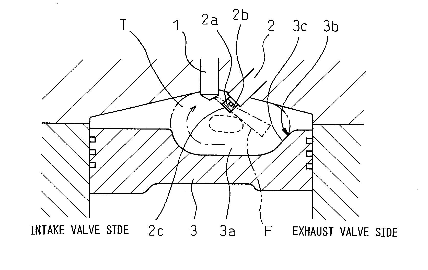
[0027]FIG. 1 is a schematic longitudinal cross-sectional view showing an embodiment of a direct fuel injection-type spark-ignition internal combustion engine according to the present invention. In the figure, 1 is a fuel injector arranged at the approximate center of the top of a cylinder for injecting fuel directly into the cylinder, and 2 is a spark plug arranged at the exhaust valve side in the vicinity of the fuel injector 5. This direct fuel injection-type spark-ignition internal combustion engine has two intake valves and two exhaust valves. FIG. 1 is a cross-sectional view passing between the two intake valves and between the two exhaust valves, so the intake valves and exhaust valves are not shown. In FIG. 1, the left side is the intake valve side. The right side is the exhaust valve side.

[0028]3 is a piston on whose top face a cavity 3a is formed biased to the exhaust valve side. The cavity 3a has a smooth inside wall suited to guiding the tumble flow. It is for guiding the...


PUM


Abstract

An engine provided with a fuel injector for directly injecting fuel into a cylinder, a spark plug positioning a spark gap in a flight path of fuel injected from the fuel injector, and a cavity formed in a piston top face, wherein at the time of stratified combustion, the fuel injector injects substantially all of the fuel in a direction merging with a tumble flow, swirling in a longitudinal direction along the cavity at the compression stroke, along the swirl direction of the tumble flow and uses the spark plug to ignite the fuel while the fuel at the end period of injection is passing through the spark gap.

Description

TECHNICAL FIELD[0001]The present invention relates to a direct fuel injection-type spark-ignition internal combustion engine.BACKGROUND ART[0002]Known in the art is stratified combustion using fuel injected in a compression stroke to form a combustible air-fuel mixture in just part of the inside of the cylinder and igniting and burning this combustible air-fuel mixture by a spark plug so as to enable combustion making the air-fuel ratio of the inside of the cylinder as a whole leaner than the stoichiometric air-fuel ratio. At the time of stratified combustion, it is necessary to position the spark gap of the spark plug inside the combustible air-fuel mixture at the ignition timing. For this, it is proposed to bias the injected fuel for forming the combustible air-fuel mixture in the spark plug direction by a cavity formed in the piston top face, but due to this, the fuel injection timing would be limited by the piston position.[0003]To enable the fuel injection timing to be set with...

Claims


Application Information

Patent Timeline
Patent Type & Authority Applications(United States)
IPC IPC(8): F02B17/00F02B5/00
CPCF02B17/005F02B23/101F02B25/18F02B2023/106Y02T10/123F02B2075/125F02D2041/389Y02T10/125F02B2023/107Y02T10/12F02B23/10F02F3/26F02M61/18F02P13/00
Inventor ASHIZAWA, TAKESHINOMURA, HIROSHITOMINO, OSAMUMAEDA, KAORUMATSUMOTO, KEISUKEKUSHIDA, TAKEO
Owner TOYOTA JIDOSHA KK
Why Eureka
Try Eureka