
Method for the transport of a civil engineering structure in an aquatic medium

a civil engineering and aquatic technology, applied in underwater structures, artificial islands, caissons, etc., can solve the problems of complex and costly work at sea, long work required at sea to assemble the various components still be required to install the civil engineering structure. complex and costly, to achieve the effect of simplifying the subsequent installation of the civil engineering structure, reducing the buoyancy, and being easy to transpor

Inactive Publication Date: 2009-07-30
SOLETANCHE FREYSSINET SA
View PDF21 Cites 20 Cited by
  • Summary
  • Abstract
  • Description
  • Claims
  • Application Information

AI Technical Summary

Benefits of technology

[0011]Stable floating of the civil engineering structure renders it particularly simple to transport.
[0012]This method of transport also makes it possible to simplify subsequent installation of the civil engineering structure. It is sufficient to bring the civil engineering structure immediately above its final position, and then to reduce its buoyancy, which has the effect of causing the civil engineering structure to descend within the aquatic medium, possibly until its base comes into contact with the floor of the aquatic medium.
[0013]The complex work at sea required for the transport and / or installation of the civil engineering structure can thus be reduced, or even eliminated.

Problems solved by technology

However the work required at sea to assemble the various components of the civil engineering structure is relatively long, complex and costly.
Even if the transport of a finished civil engineering structure by sea were to be envisaged, for example by placing it entirely on a boat or on a barge, complex work at sea would still be necessary to install the civil engineering structure in its permanent position.

Method used


Image

  • Method for the transport of a civil engineering structure in an aquatic medium
  • Method for the transport of a civil engineering structure in an aquatic medium
  • Method for the transport of a civil engineering structure in an aquatic medium

Examples


Embodiment Construction

[0043]An aim of the invention is to transport a civil engineering structure in an aquatic medium, for example at sea. Other aspects of the invention relate to the launching and / or installation of the civil engineering structure in an aquatic medium.

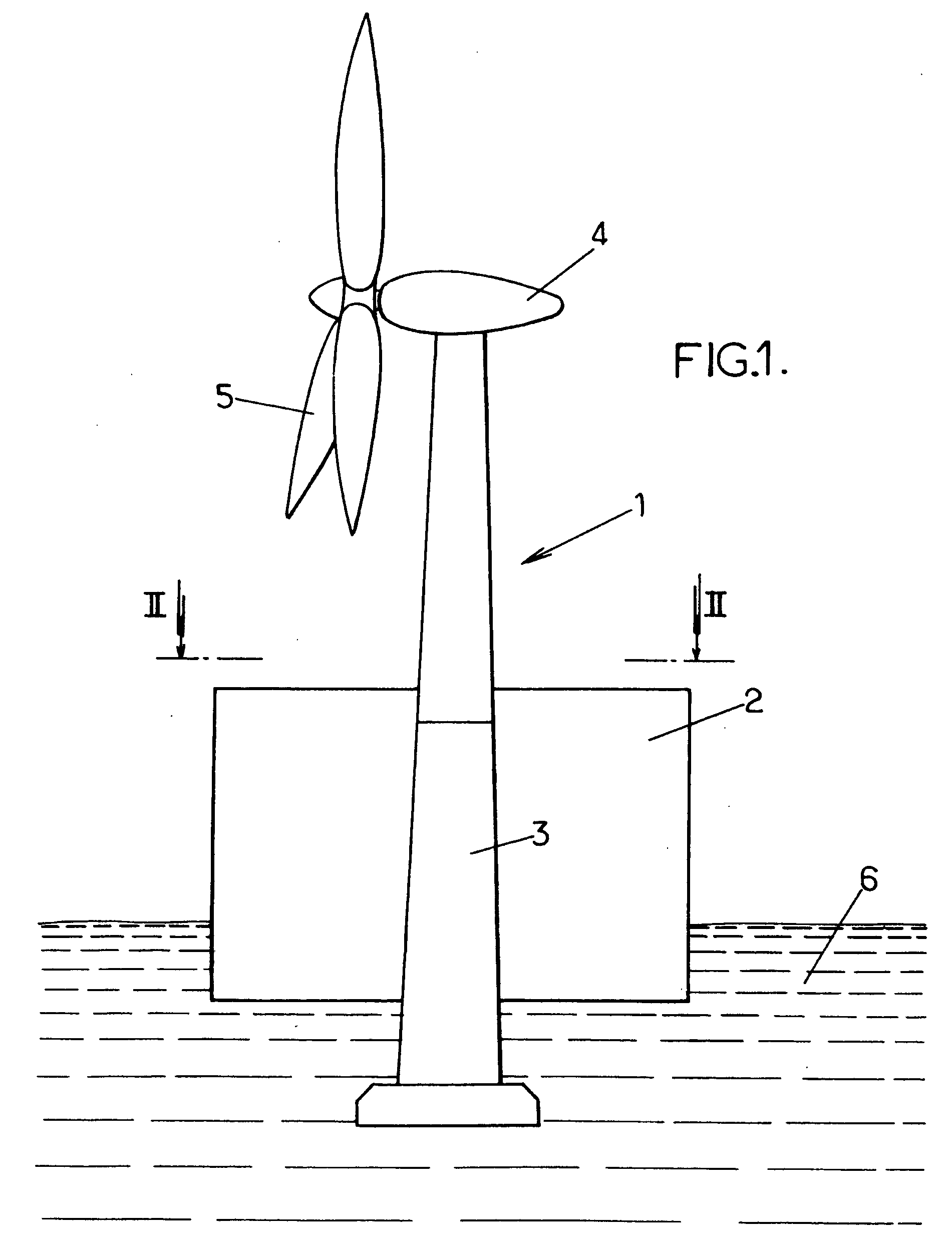
[0044]The civil engineering structure in question may be any type of gravity structure. Advantageously its height is greater than the dimensions of its base. It may for example be an offshore wind generator, that is to say a wind generator which is designed to be located in the open sea.

[0045]The non-restrictive embodiment of an offshore wind generator is more particularly considered below purely for illustrative purposes.

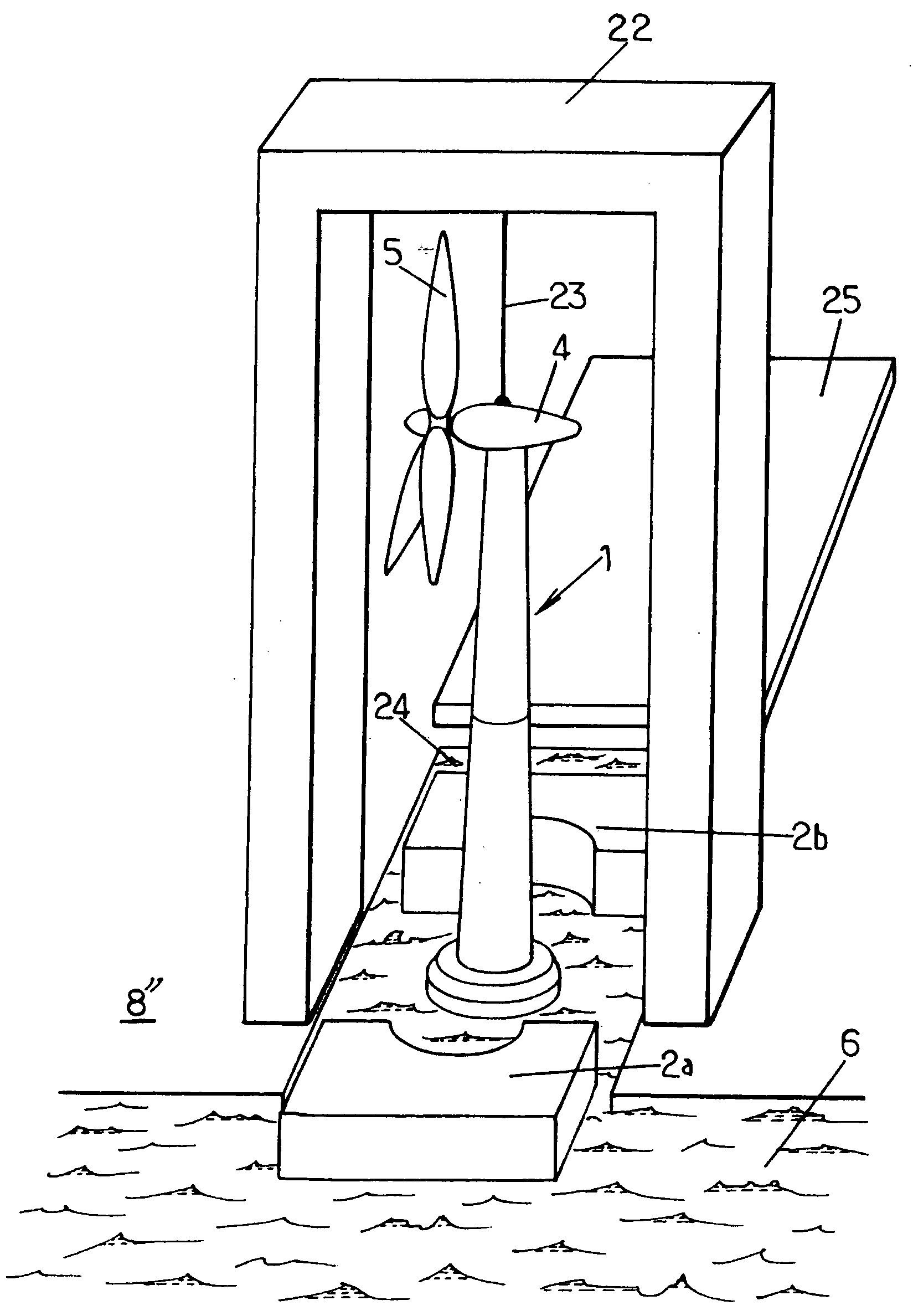
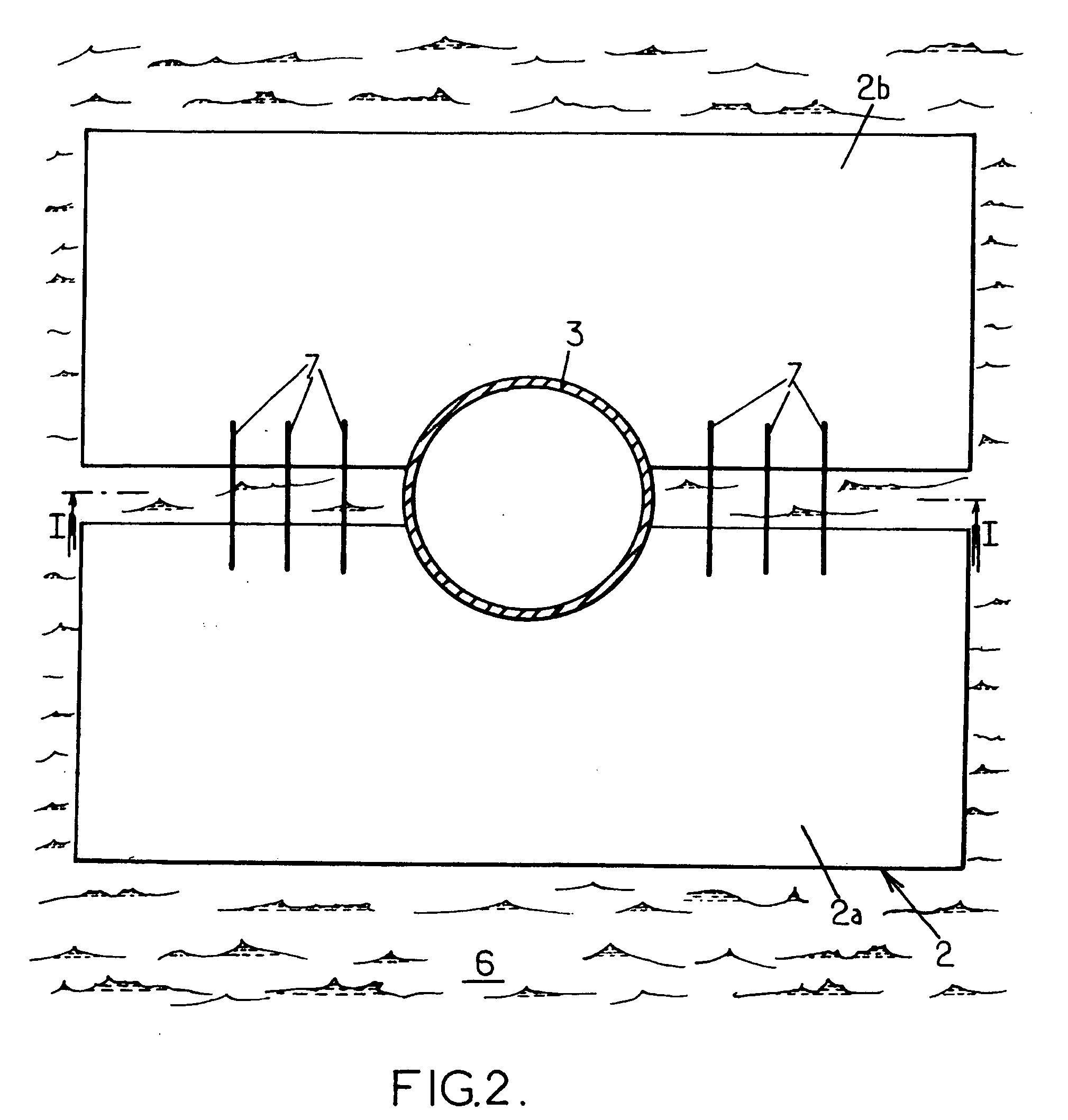
[0046]As shown in FIGS. 1 and 2, a float 2 is associated with a wind generator 1 comprising a lower portion 3 including a base and possibly a metal drum, surmounted by a nacelle 4 incorporating a hub bearing the blades of a rotor 5, to ensure that the wind generator floats stably in the sea. This association may possibly...


PUM


Abstract

The invention provides a method for the transport of a civil engineering structure in an aquatic medium. According to this method: at least one float is associated with the civil engineering structure in such a way as to ensure that the said civil engineering structure floats stably in an aquatic medium, the said float surrounding the civil engineering structure and a bottom portion of the civil engineering structure extending below the said float, and the civil engineering structure and the associated float are caused to move in the aquatic medium to a desired position.

Description

BACKGROUND OF THE INVENTION[0001]This invention relates to the transport of a civil engineering structure in an aquatic medium. Other aspects of the invention will relate to launching and / or installation of the civil engineering structure in an aquatic medium.[0002]For reasons of simplicity it is common practice not to transport finished civil engineering structures by sea, but separate components which will then be assembled at sea.[0003]By way of example, the construction of an offshore wind generator, that is to say one which is intended to be located in the open sea, conventionally takes place in the following way—the base and possibly the metal drum of the wind generator are constructed onshore, they are transported to sea holding them by means of a crane located on a barge, and then once at sea the hub and the blades forming the rotor of the wind generator are positioned on the base and / or metal drum.[0004]However the work required at sea to assemble the various components of ...

Claims


Application Information

Patent Timeline
Patent Type & Authority Applications(United States)
IPC IPC(8): B63B35/00E02B17/00
CPCB63B35/003Y02E10/727E02B2017/0091E02B17/027E02B2017/0039E02B2017/0069B63B77/10E02B17/00
Inventor STUBLER, JEROMELEBON, JEAN-DANIELPETIT, SEBASTIEN
Owner SOLETANCHE FREYSSINET SA
Learn More