
Speed calculation system

a technology of speed calculation and communication path, applied in data switching networks, frequency-division multiplexes, instruments, etc., can solve the problems of reducing the bandwidth of communication caused by the probe packet, and so as to achieve the effect of reducing the communication bandwidth

Inactive Publication Date: 2009-07-30
NEC CORP
View PDF17 Cites 9 Cited by
  • Summary
  • Abstract
  • Description
  • Claims
  • Application Information

AI Technical Summary

Benefits of technology

[0068]In accordance with the present invention, embedding probe information into actual data, i.e. a data packet, which passes trough the communication path that becomes an object of speed calculation, instead of generating the probe packet dedicated for calculating the speed, enables oppression upon the bandwidth for communication caused by the probe packet to be reduced.
[0069]Further, in accordance with the present invention, inserting the probe information into the data packet, being the actual data, to transmit two data packets at a time, instead of generating the probe packet (dummy packet) dedicated for calculating the speed, enables the calculation of the speed without oppressing the bandwidth even in a narrow-bandwidth path where the speed fluctuates dynamically, of which the practical speed calculation is difficult, for example, a wireless link etc.
[0070]Further, in accordance with the present invention, in a connection between two nodes including a plurality of paths each of which is an object of calculation, arranging distribution of the data packets to the path two by two enables the calculation of the speed of each path.
[0071]Yet further, in accordance with the present invention, in a case where two nodes are connected by means of a plurality of the communication paths, selecting the communication path of which a communication load is small enables oppression upon the communication bandwidth to be reduced.

Problems solved by technology

The packet train technique, which is a technique of successively transmitting two or more packets, does not necessarily provide a discrete mode of calculation results as in the case of the packet pair technique; nevertheless, a sufficient long measurement duration allows measurement values that converge to a single value.

Method used


Image

  • Speed calculation system
  • Speed calculation system
  • Speed calculation system

Examples


embodiment 1

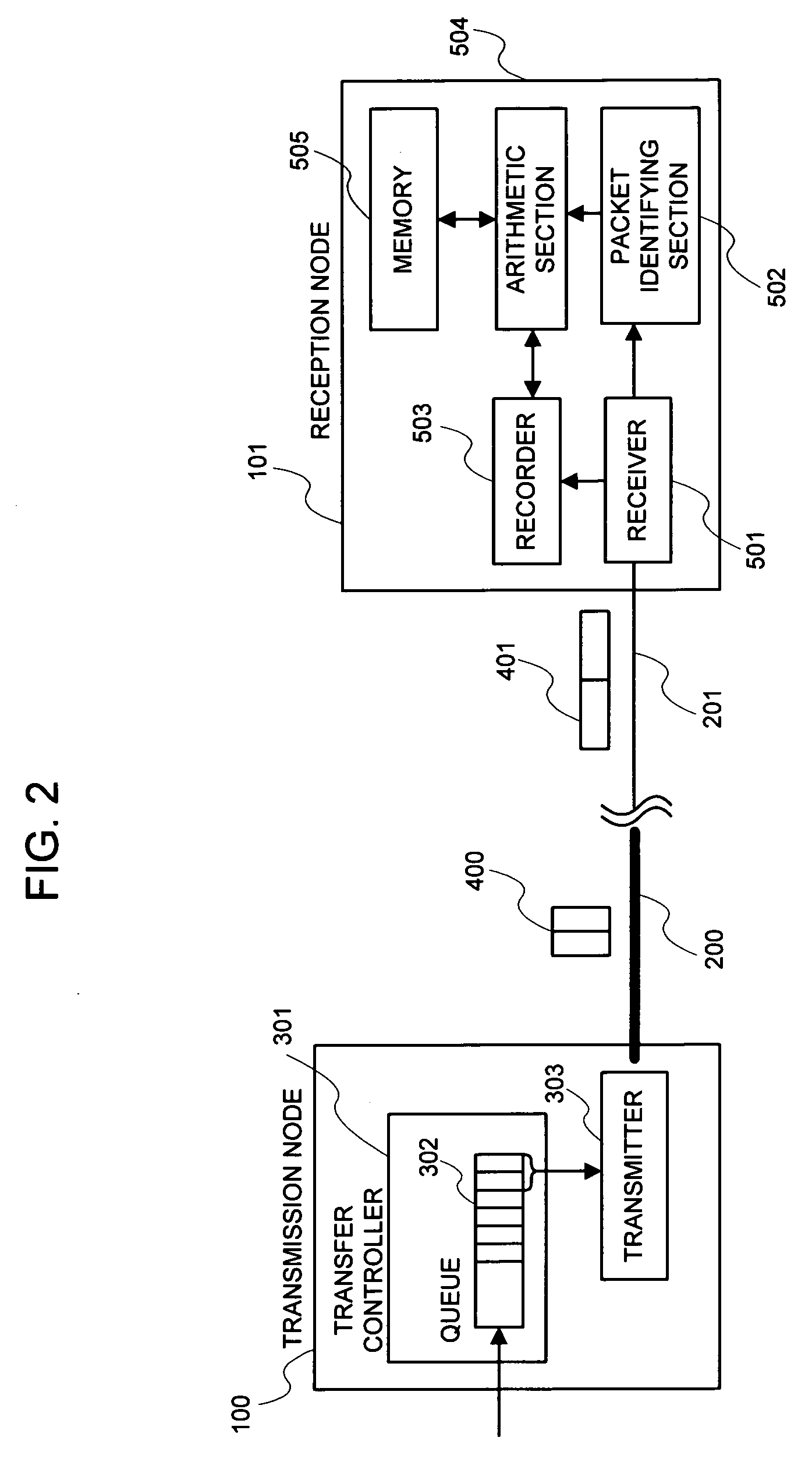
[0104]The embodiment 1 in the present invention will be explained. FIG. 2 is a detailed view of the system of the present invention.

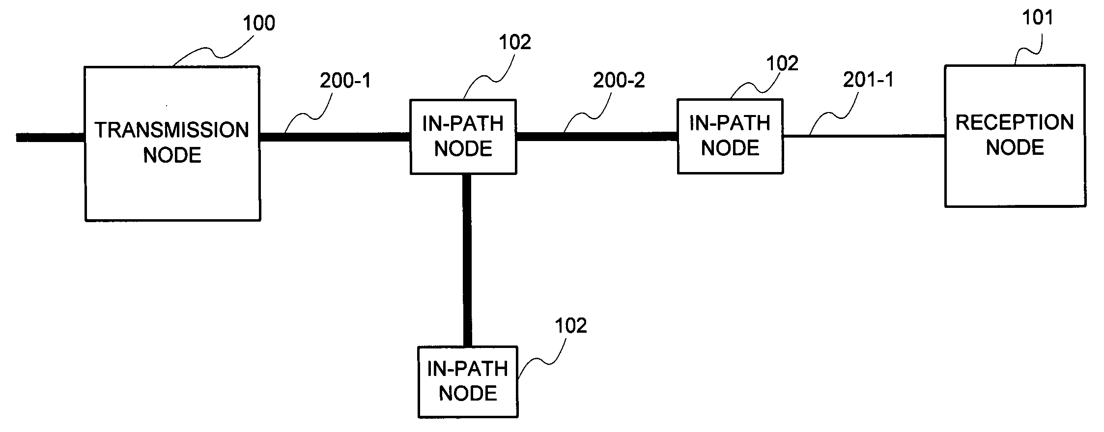
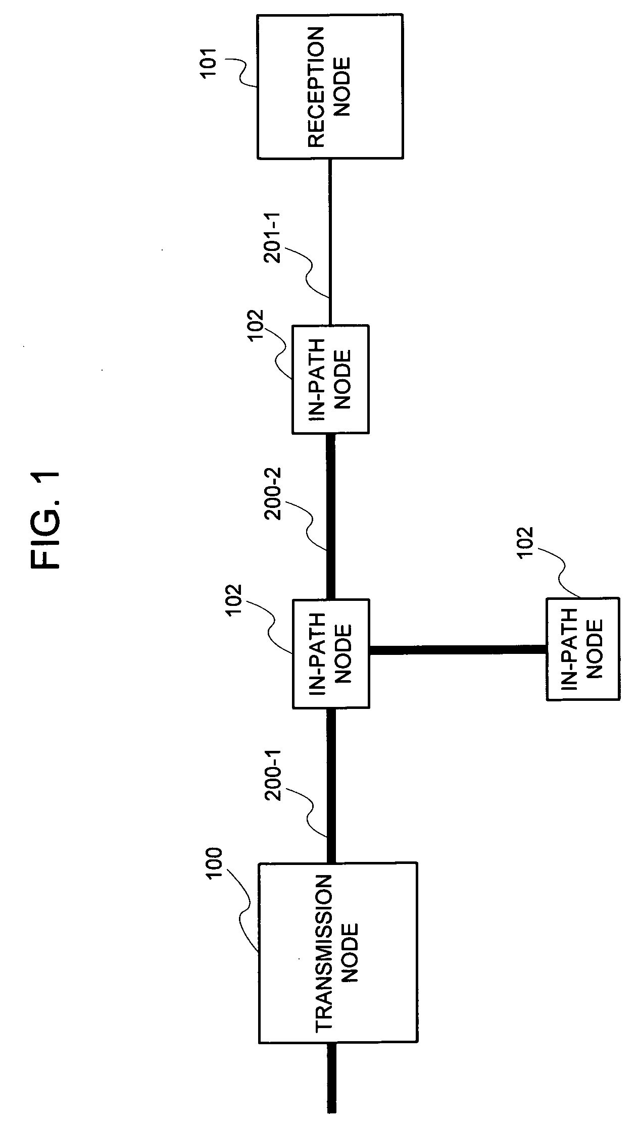
[0105]Upon making a reference to FIG. 2, the embodiment of the present invention is configured of the transmission node 100 and the reception node 101. Further, the transmission node 100 and the reception node 101 are connected by means of a high-speed link 200 and a low-speed link 201, being a path that is an object of speed calculation respectively.

[0106]The transmission node 100 is configured of a transfer controller 301 and a transmitter 303.

[0107]The transfer controller 301 receives the data packet that arrives at a random timing. This so-called packet is a data packet of which a payload portion has the actual data inserted. The received data packet is filed in a queue 302, which the transfer controller 301 has, for the time being. Further, the transfer controller 301 groups at least two data packets and transfers the data packets to the transmitte...

embodiment 2

[0122]In the above-mentioned embodiment 1, the case of placing no qualification as to which packet group, out of the grouped data packets, was employed for the probe, was explained. That is, all data packets may be grouped and employed for the probe, and the probe information may be inserted into a certain proportion of the data packets out of all data packets. However, as a matter of fact, it is also thinkable that no packet is input for a long time. Thereupon, in the second embodiment, the system allowing the speed calculation of the path to be continued also in such a case will be explained.

[0123]FIG. 5 is a configuration view in the embodiment 2. Additionally, the identical number is affixed to the component similar to that of the foregoing embodiment, and detailed explanation is omitted.

[0124]A transfer controller 301 includes a dummy generator 304, a dummy timer 306, and a dummy timer 307 in addition to the components explained in the foregoing embodiment.

[0125]In a case where...

embodiment 3

[0139]In the foregoing embodiment, the case of connecting the transmission node 100 and the reception node 101 by means of a singular path that was an object of speed calculation was explained.

[0140]In the embodiment 3, the case where a plurality of the paths each of which is an object of speed calculation exist between the transmission node and the reception node will be explained.

[0141]FIG. 7 is a view illustrating a network in a case of calculating the speed of plural paths. Additionally, the identical number is affixed to the component similar to that of the foregoing embodiments, and detailed explanation is omitted.

[0142]Upon making a reference to FIG. 7, the embodiment of the present invention is configured of a transmission node 120 and a reception node 121, and the transmission node 120 and the reception node 121 are connected by means of a plurality of the paths each of which is an object of speed calculation. Of these paths, one path is a path including a high-speed link 2...


PUM


Abstract

In the prior art, in a case of measuring a speed of a narrow-bandwidth path of which the state fluctuates dynamically, a serious influence is placed upon a speed calculation with a sufficient precision, and a performance.Embedding probe information into a data packet, being actual data, to transfer two at a time allows the data packet having the probe information embedded to act as a probe packet of the packet pair technique as well. Further, in a system including a plurality of the paths, the data packets are distributed to the path two packets by two packets.

Description

TECHNICAL FIELD[0001]The present invention relates to a technology for calculating a communication speed of a communication path, and more particularly, to a technology for inserting probe information into a received packet to be transmitted, thereby to calculate a speed of a path that is an object of calculation.BACKGROUND ART[0002]In general, there exists a packet pair technique as a conventional example of calculating the communication speed of the communication path that goes through a series of paths (links) and intermediate nodes.[0003]In the packet pair technique, the communication speed of the path, which is comprised of high-speed and low-speed links connecting a transmission node and a reception node, is the object of calculation. The transmission node successively transmits two probe packets (packet pair) dedicated for calculating the speed of the path that is an object of calculation, and the speed of the path is derived from a difference between arrival times of two pac...

Claims


Application Information

Patent Timeline
Patent Type & Authority Applications(United States)
IPC IPC(8): H04L12/26H04L12/70H04L29/08
CPCH04L12/2697H04L43/0888H04L45/22H04L43/50H04L45/00H04L43/10H04L45/06
Inventor NAKATA, TSUNEO
Owner NEC CORP
Learn More