
Multi-function flashlight

a flashlight and multi-functional technology, applied in the field of multi-functional flashlight assemblies, can solve the problems of difficult to operate in the typical military environment, difficult to integrate the flashlight, and small buttons, sliders and knobs are nearly impossible to operate in a reliable fashion, so as to facilitate the integration of the flashlight and facilitate operation

Inactive Publication Date: 2009-07-30
EMISSIVE ENERGY A DELAWARE
View PDF4 Cites 21 Cited by
  • Summary
  • Abstract
  • Description
  • Claims
  • Application Information

AI Technical Summary

Benefits of technology

"The present invention is a flashlight assembly that offers multi-functionality and is easy to operate and maintain. The flashlight has an outer housing that can be integrated with a firearm and serves as a handgrip for holding the firearm. The flashlight head has a high-output white LED and four colored LEDs around the periphery of the lens. The control for the flashlight is provided by a momentary switch and a variable resistance switch. The flashlight interface includes bus bars and a resistive element to determine the manner in which the flashlight will operate. The flashlight is modular in construction and interchangeable parts can be easily maintained. The technical effects of the invention are improved flashlight construction with multi-functionality, ease of operation, and high degree of reliability even in the most rugged environment."

Problems solved by technology

The difficulty is that such an interface is bulky and is prone to snagging on things as the solider quickly moves in a combat situation.
Other difficulties with such flashlights include the fact that they are typically single function devices that must be exchanged for a different flashlight should the need for an additional function arise, such as for example, in infra-red applications.
In addition, should a flashlight include multi-functional features, often the controls are small and fussy making them difficult to operate in the typical military environment where the user is often wearing gloves.
In these applications small buttons, sliders and knobs are nearly impossible to operate in a reliable fashion.

Method used


Image

  • Multi-function flashlight
  • Multi-function flashlight
  • Multi-function flashlight

Examples


first embodiment

[0034]Turning now to FIGS. 6 and 7, the details of the construction of a first embodiment user interface 22 for the flashlight 10 are shown. The circuit board 68 includes an adjustable resistance type structure one or both of the continuous strips 78 are resistive strips formed on the surface thereof and the rotary actuator 60 includes a wiper 66 affixed to the end thereof that bridges between the two resistance strips 68. While in the context of the present invention, resistance will be used hereinafter as the signal being generated, the principal of the present invention is directed to using electronic devices having a measurable value wherein a measured value corresponding to the electronic device provides the signal that is read. In this regard, the electronic devices could be any such device having a measurable value such as for example, resistors, capacitors or inductors. Accordingly, while for the remainder of this specification, the signal will be referred to as resistance v...

second embodiment

[0037]Turning now to FIG. 8, the details of a second embodiment user interface 122 for the flashlight 10 are shown. While this embodiment still employs the momentary contact 62, the continuous resistive strips on the circuit board are replaced with a circuit board 168 containing plurality of individual contact pads 178 in indexed positions. A plurality of resistors 179 having different resistive values are arranged such that each of the resistors 179 is positioned in electrical communication with the indexed contact pads 178. When the wiper 66 is rotated into position so that it is in contact with the contact pads 178, a signal is provided that corresponds to a fixed and known resistive value corresponding to the resistor 179 in that position. In this regard, each rotation of the user interface 122 to an indexed location moves the wiper 66 into a fixed resistance position that is read by the operational circuit of the flashlight and is used to execute a predetermined operational com...

third embodiment

[0038]Turning now to FIG. 9, the details of a third embodiment user interface 222 for the flashlight are shown. In this embodiment, the rotary selector and the momentary contact are removed and a wire 224 is extended out from the user interface 222 to a tape switch 226 arrangement. The tape switch 226 includes two push buttons 228, 230. The flashlight technology of the present invention allows the flashlight to be adaptive to the particular user interface that is installed thereon thereby allowing the flashlight itself to sense whether the interface is actually a rotary interface or a tape switch interface. The two buttons 228, 230 on the tape switch 226 are in electrical communication with the bus bars 50a, 50b and 50c and serve to send a signal to the flashlight along the bus bars in the same fashion as does the rotary actuator. This interface 222 is constructed to be modular so that it can be interchanged with the user interface 22 and 122 embodiments described above. In operatio...


PUM


Abstract

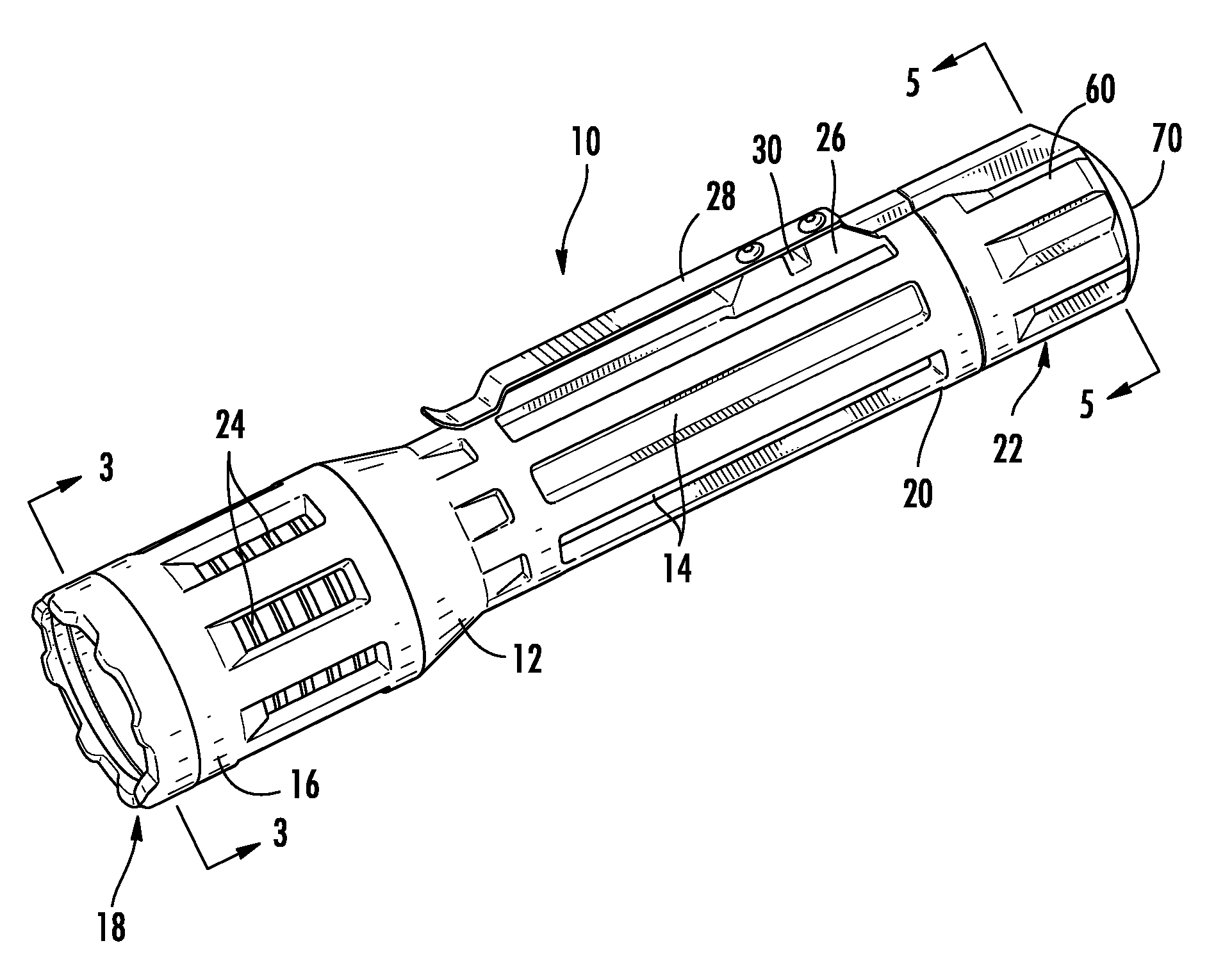
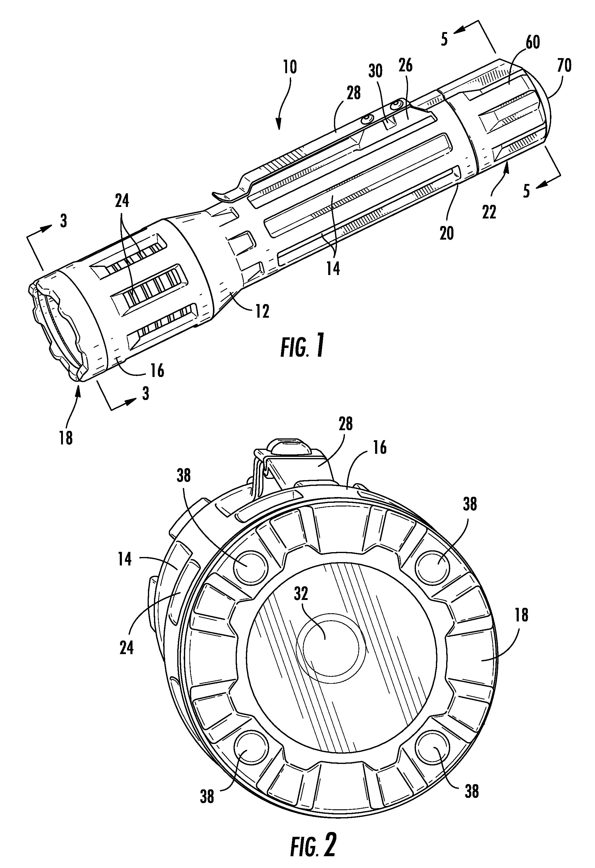
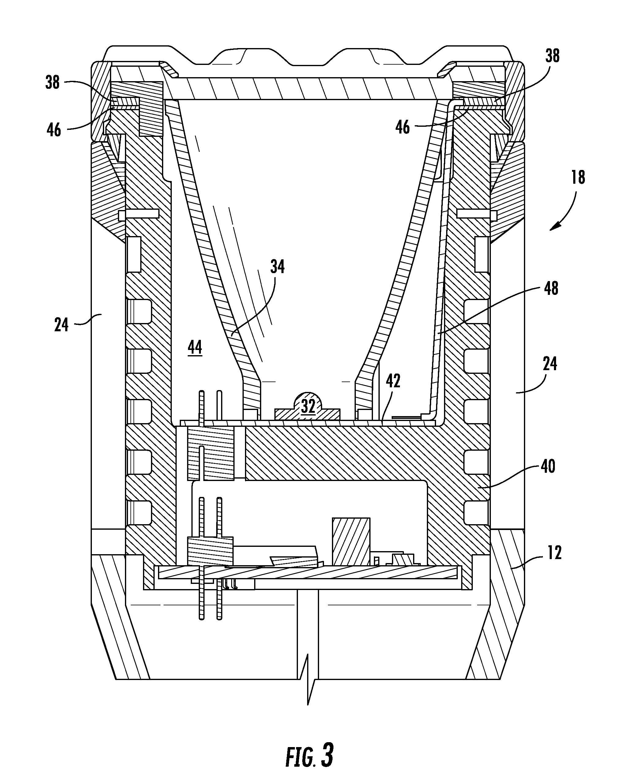
A multi-function flashlight device is provided in either an all white light emitting diode (LED) or a colored LED version that allows versatile functionality. The flashlight is fashioned to have an outer housing that includes both an integrated means for interfacing the flashlight with a firearm and a surface thereon that serves as a handgrip. The outer housing of the flashlight is configured to be engaged by a clamping assembly that facilitates integration of the flashlight with standard firearm accessory rail assemblies. The flashlight head includes a high-output white LED positioned centrally within an optical element such as a reflector. Should the flashlight be a colored light, four other positions are provided around the periphery of the lens that contain colored LEDs. The flashlight provides the user the ability to selectively and individually control the mode of operation for all of the LEDs contained therein.

Description

CROSS-REFERENCE TO RELATED APPLICATIONS[0001]This application is related to and claims priority from earlier filed U.S. Provisional Patent Application No. 61 / 024,293, filed Jan. 29, 2008.BACKGROUND OF THE INVENTION[0002]The present invention relates generally to multi-functional flashlight assemblies. More specifically, the present invention relates to a multi-functional flashlight assembly that includes a unique switching mechanism that provides a plurality of different functions while also exhibiting ease of use and increased durability even in rugged use environments, such as those encountered in military applications[0003]In the prior art, flashlights for use in military applications have typically been constructed in a standard fashion with a large diameter tubular outer housing. As a consequence, such a flashlight required a large mounting assembly in order to facilitate mounting of the flashlight onto a weapon such as an M-16 rifle. Generally, modern type firearms include suc...

Claims


Application Information

Patent Timeline
Patent Type & Authority Applications(United States)
IPC IPC(8): F21L4/04
CPCF21L4/00F21L4/027F21V9/083F21V23/0421F21V29/70F21Y2101/02F41G1/35F41G11/003Y10S362/80F21V29/004F21Y2115/10F21V29/89
Inventor GALLIO'BRIEN, CHRISTOPHER J.CALVINO, ALEXANDER
Owner EMISSIVE ENERGY A DELAWARE
Learn More