Tank opening-closing device

Inactive Publication Date: 2009-07-30
TOYODA GOSEI CO LTD
View PDF2 Cites 18 Cited by
  • Summary
  • Abstract
  • Description
  • Claims
  • Application Information

AI Technical Summary

Benefits of technology

[0007]An advantage of some aspects of the invention is to provide a tank opening-closing device with a simple constitution for which the operating force for doing the opening operation of the valve opening-closing mechanism during fueling can be small.
[0011]The operating force of the fueling gun or the like during fueling is not applied directly to the valve opening-closing mechanism, but rather is applied indirectly to the valve opening-closing mechanism via the operating member of the opening-closing activation mechanism, so it is possible to maintain a high level of sealing integrity without applying a large force biased toward the valve opening-closing mechanism which has a seal portion.
[0012]Also, for the opening-closing member of the valve opening-closing mechanism to close the inlet with a high level of sealing integrity, it is necessary to make the force in the closing direction by the spring larger. Also, when directly pressing the opening-closing member of the valve opening-closing mechanism using the fueling gun, as the fueling gun is inserted in the fuel path, the position at which the opening-closing member is pressed approaches the axially supported location, and a large force is required to do the opening operation of the opening-closing member. However, the present invention is able to increase the moment by arranging the opening-closing member at a distance away from the axially supported location, and thus it is possible to quickly do the opening operation of the opening-closing member even when the operating force of the fueling gun is small.
[0013]Furthermore, the opening-closing activation mechanism receives the insertion force of the fueling gun, and directly presses the valve opening-closing mechanism, so it is not necessary to provide the link mechanism that links the valve opening-closing mechanism, and it is possible to have an easy constitution and use a small number of parts.
[0015]Application example 3 can have a constitution for which the operating member is equipped with a guide recess consisting of a curved surface pressed so as to rotate the operating member while sliding the tip part of the fueling gun when the operating member is pressed by the tip part of the fueling gun. With this constitution, the opening-closing activation mechanism does guiding while the guide recess of the operating member slides the tip of the fueling gun, as well as so as to face the fueling gun toward the center of the operating member, so the insertion force of the fueling gun is conveyed efficiently to the valve opening-closing mechanism, and thus the valve opening-closing mechanism undergoes the opening and closing operation smoothly. In fact, the guide recess guides the fueling gun to the desired position of the fuel path, so the fueling work is also smooth.
[0016]Application example 4 can have a constitution for which the opening-closing member is equipped with a pressure regulating valve for regulating inner pressure of the fuel tank and atmospheric pressure within a preset range. With this constitution, it is possible to easily attach the pressure regulating valve to the opening-closing member of the valve opening-closing mechanism.

Problems solved by technology

This kind of fuel cap not only has poor operability because a plurality of rotation operations is required when fueling, but there was also the problem that when removed, one could forget where the cap was left or could forget to close the cap, so it was necessary to come up with a means for preventing loss.
However, with the conventional fueling device, the first closing body is pressed by the fueling gun, and there was the problem that the force when doing the opening operation of the second closing body is large, so the fueling operability was poor.
Also, there was the problem that the link mechanism for having the first closing body and the second closing body move in conjunction is complex, and this means there is a large number of parts.
Also, when directly pressing the opening-closing member of the valve opening-closing mechanism using the fueling gun, as the fueling gun is inserted in the fuel path, the position at which the opening-closing member is pressed approaches the axially supported location, and a large force is required to do the opening operation of the opening-closing member.

Method used


Image

  • Tank opening-closing device
  • Tank opening-closing device
  • Tank opening-closing device

Examples


first embodiment

A. First Embodiment

[0033](1) Schematic Structure of the Tank Opening-Closing Device

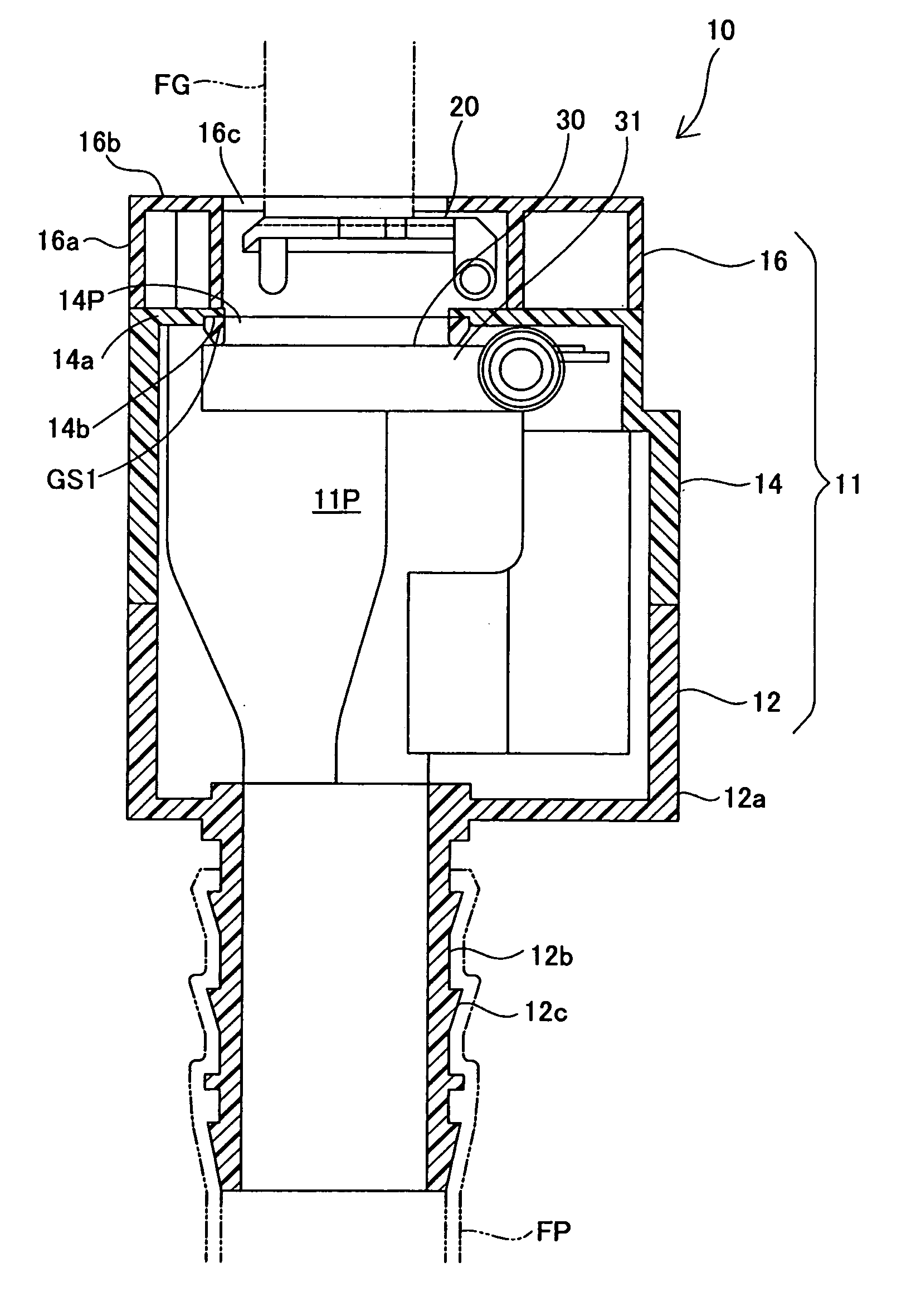
[0034]FIG. 1 is a cross section view in the axis direction of the tank opening-closing device of the first embodiment of the present invention. The tank opening-closing device 10 is a mechanism for supplying fuel to the fuel tank (not illustrated) without using a fuel cap, in other words, it is a mechanism for supplying fuel to a fuel tank from a fueling gun by opening and closing the fuel path with the external force or the like from the fueling gun after opening the fueling lid (not illustrated). Following, we will give a detailed description of the constitution of the tank opening-closing device.

[0035](2) Constitution of Each Part

[0036]The tank opening-closing device 10 is equipped with the tank opening forming member 11 having the fuel path 11P connected to the fuel tank, the opening-closing activation mechanism 20, and the valve opening-closing mechanism 30 that opens and closes the inlet 14P.

[00...

second embodiment

B. Second Embodiment

[0054]FIG. 7 is a cross section view showing the tank opening-closing device 100 of the second embodiment. The tank opening-closing device 100 of the second embodiment is characterized by a constitution with which a pressure regulating valve is housed in the valve opening-closing mechanism 130 supported to be able to rotate on the tank opening forming member 111. The opening-closing activation mechanism 120 has the same constitution as that of the first embodiment, and the valve opening-closing mechanism 130 is opened and closed by the insertion of the fueling gun FG.

[0055]FIG. 8 is a cross section view showing the upper part of the tank opening-closing device 100. The valve opening-closing mechanism 130 is equipped with a valve body 132, a valve support moving body 134, and a spring 136. The valve body 132 is equipped with a pressing member 132a for pressing on the opening-closing activation mechanism 120 (FIG. 7), the sealing body 132b formed on the outer perip...

third embodiment

C. Third Embodiment

[0060]FIG. 12 is a cross section view showing the tank opening-closing device 200 of the third embodiment, and FIG. 13 is a cross section view showing the valve opening-closing mechanism 230. The tank opening-closing device 200 of the third embodiment is characterized by having a constitution for which a pressure regulating valve constituted from a positive pressure valve and a negative pressure valve as well as a gasket GS3 are attached to the valve opening-closing mechanism 230. Specifically, the valve opening-closing mechanism 230 is equipped with a valve support moving body 231, the valve body 232, the spring 238, the gasket GS3, the positive pressure valve 240 and the negative pressure valve 250 constituting the pressure regulating valve. The valve body 232 is equipped with the pressing member 233 having the pressing part 233a for being pressed by the opening-closing activation mechanism 220 (FIG. 12) and the valve main body 234 for holding the pressing membe...


PUM


Abstract

The tank opening-closing device is equipped with a tank opening forming member having a fuel path for leading fuel supplied from the fueling gun through the inlet to the fuel tank, a valve opening-closing mechanism having an opening-closing member and spring that closes in a state with the inlet sealed, and an opening-closing activation mechanism for opening and operating the opening-closing member. The opening-closing activation mechanism has an operating member pivoted at the tank opening forming member, and a pressing member for pressing the opening-closing member formed on the operating member, and is constituted so that by the operating member being pressed by the fueling gun and rotating, the opening-closing member is pressed by the pressing member and is rotated in the opening direction so as to open the inlet.

Description

[0001]This application claims the benefit of and priority from Japanese Application No. 2008-13473 filed January 24, the content of which is incorporated herein by reference.BACKGROUND OF THE INVENTION[0002]1. Field of the Invention[0003]The present invention relates to a tank opening-closing device for fueling a fuel tank through a fuel path, and particularly to a mechanism for opening and closing the fuel path.[0004]2. Description of the Related Art[0005]The inlet of the inlet pipe for fueling an automobile is typically sealed by a fuel cap that is attached and detached by a rotation operation. This kind of fuel cap not only has poor operability because a plurality of rotation operations is required when fueling, but there was also the problem that when removed, one could forget where the cap was left or could forget to close the cap, so it was necessary to come up with a means for preventing loss. To address these kinds of problems, the fueling device noted in International Paten...

Claims


Application Information

Patent Timeline
IPC IPC(8): F16K51/00
CPCB60K15/04B60K2015/0429B60K15/0406
Inventor HAGANO, HIROYUKINAKAGAWA, MASAYUKI
Owner TOYODA GOSEI CO LTD
Why Eureka
Try Eureka