
Method And System For Completing A Well

a well and well technology, applied in the field of well completion methods and systems, can solve the problems of limited success of attempts, and achieve the effect of facilitating the detection and measurement of formation properties

Inactive Publication Date: 2009-07-30
SCHLUMBERGER TECH CORP
View PDF9 Cites 21 Cited by
  • Summary
  • Abstract
  • Description
  • Claims
  • Application Information

AI Technical Summary

Benefits of technology

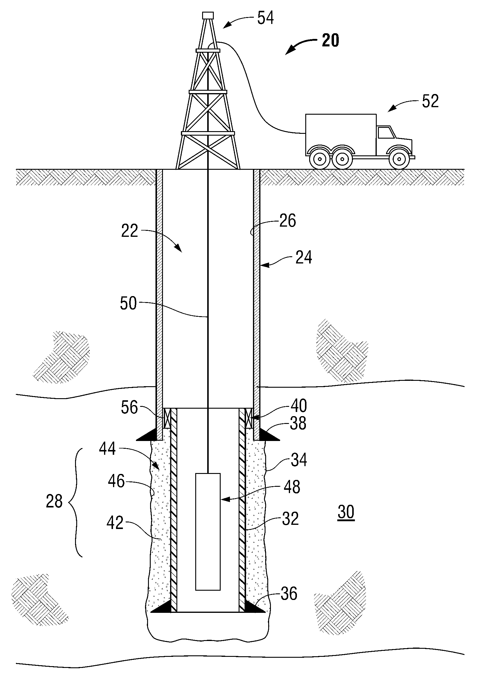
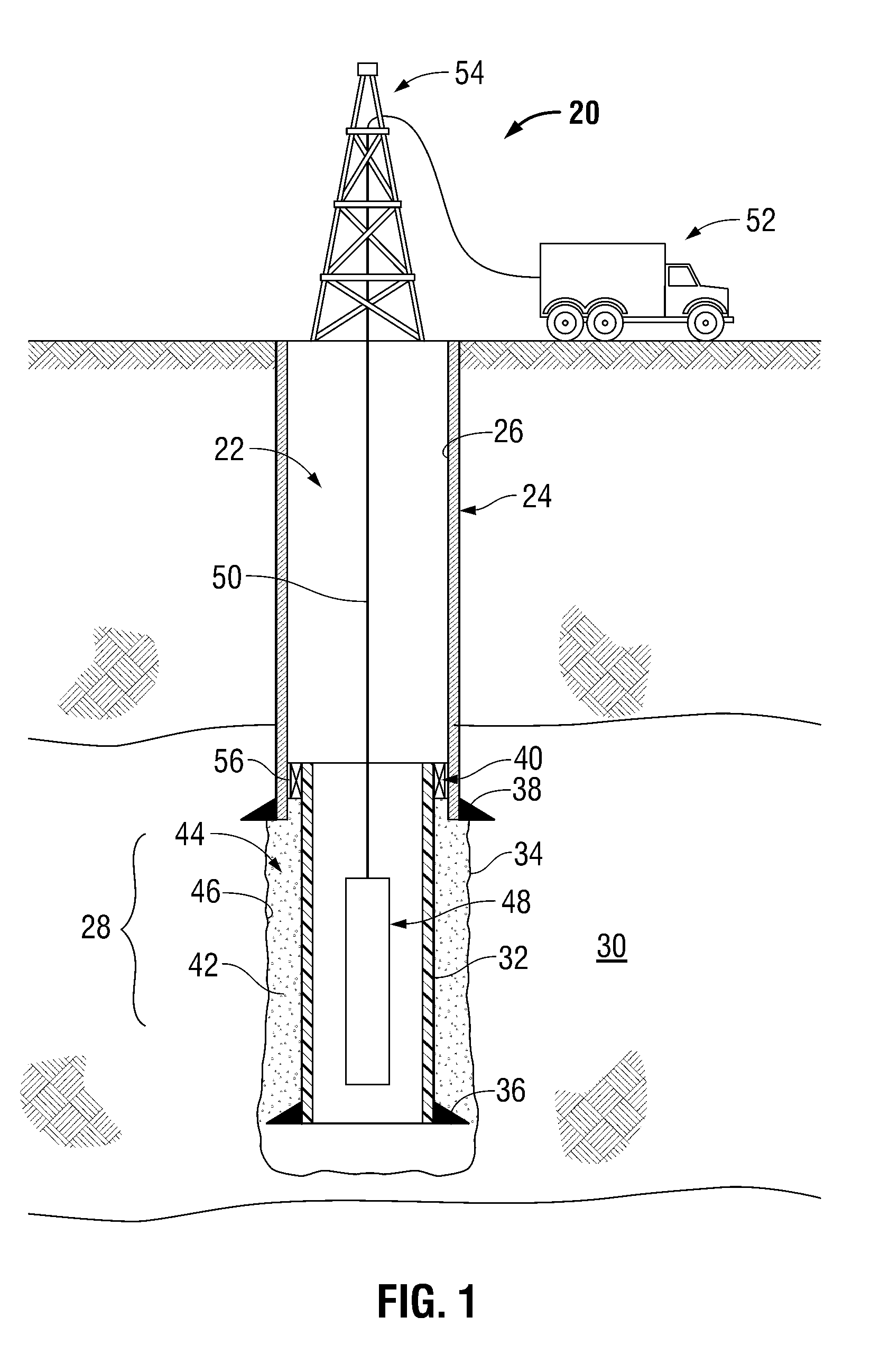
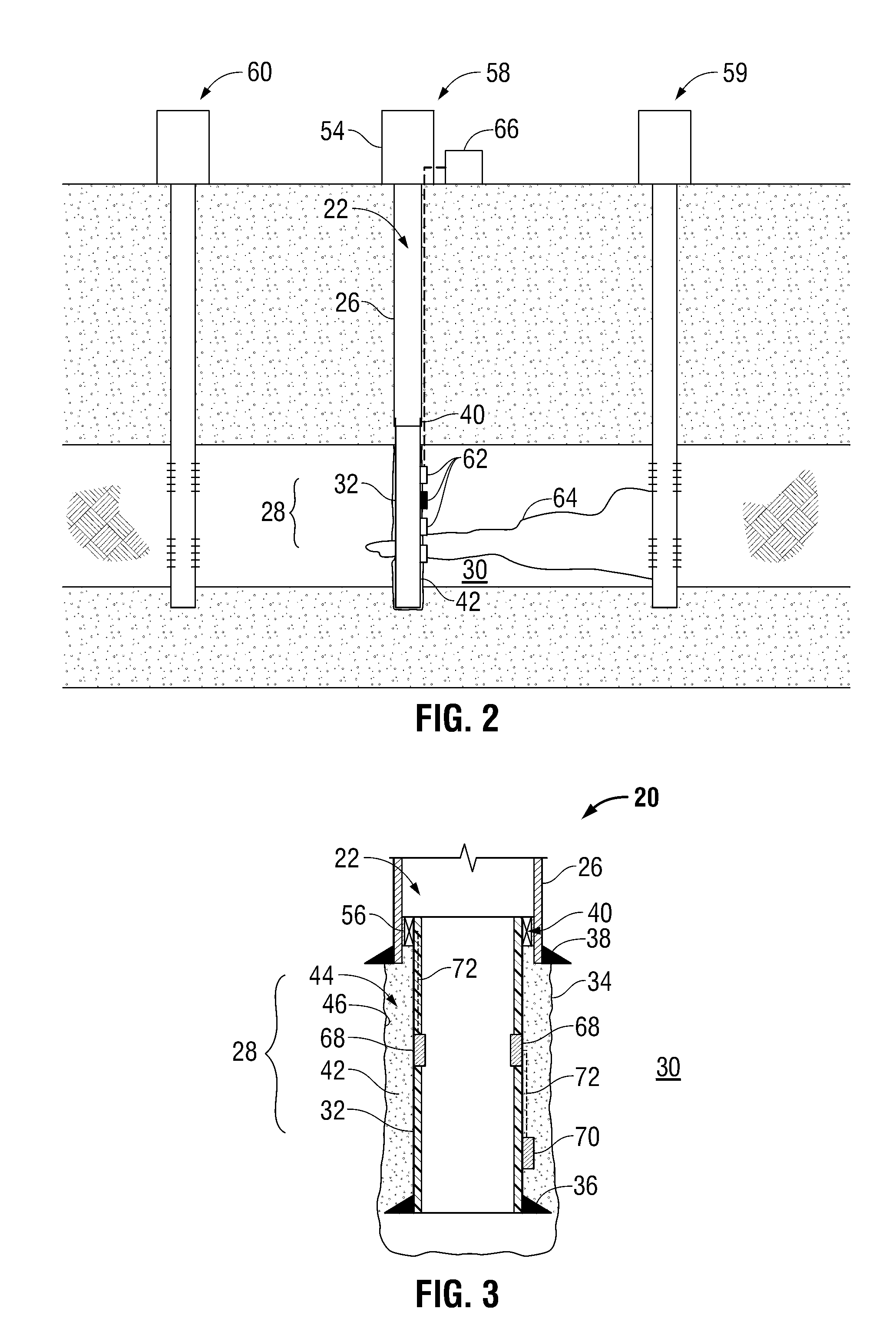
[0006]In general, the present invention provides a system and methodology for facilitating the detection and measurement of formation properties with various measurement devices, such as logging tools. The technique comprises locating a standard tubular, e.g. casing, in a well proximate a zone of interest to be logged. A tubing that is transparent to signals associated with logging tools, e.g. non-metallic and non-magnetic casing or liner, is attached to the standard tubing so as to extend along the zone of interest. Additionally, a protective material is directed to the region adjacent the transparent tubing to protect the transparent tubing from detrimental contact with deleterious well fluid.

Problems solved by technology

If logging tools are used to detect and measure formation properties, the logging techniques are carried out in an open hole completion because standard casings interfere with the logging measurements.
Attempts have been made to utilize casings that do not interfere with operation of the logging tools, however such attempts have met with limited success often due to the extremely harsh wellbore environment.

Method used


Image

  • Method And System For Completing A Well
  • Method And System For Completing A Well
  • Method And System For Completing A Well

Examples


Embodiment Construction

[0016]In the following description, numerous details are set forth to provide an understanding of the present invention. However, it will be understood by those of ordinary skill in the art that the present invention may be practiced without these details, and that numerous variations or modifications from the described embodiments may be possible.

[0017]The present invention relates to a system and method for completing a well. For example, the system and method can be used for drilling and completing observation wells used in enhanced oil recovery applications. Generally, standard metal tubing is used in combination with one or more sections of transparent tubing, which may be non-metallic, non-magnetic tubing that is transparent with respect to signals associated with measurements made by logging tools. The standard tubing and the transparent tubing may comprise a variety of casings, including liners, used in observation wells or other suitable wells. Additionally, a material, suc...


PUM


Abstract

A technique facilitates the detection and measurement of formation properties with various measurement devices, such as logging tools. The technique comprises locating a standard tubular in a well such that the standard tubular extends to a zone of interest with respect to a logging procedure. A transparent tubing is attached to the standard tubing so as to extend along the zone of interest. Additionally, a protective material is directed to the region adjacent the transparent tubing to protect the transparent tubing from detrimental contact with deleterious well fluid.

Description

BACKGROUND OF THE INVENTION[0001]1. Field of the Invention[0002]In many oil production operations, enhanced oil recovery techniques are employed to facilitate oil production. Many enhanced oil recovery projects use thermal recovery methods in which steam is injected to enable recovery of heavy oil. Production from heavy oil reserves is expanding worldwide.[0003]During enhanced oil recovery operations, formation properties are monitored at different locations within a reservoir. The monitored formation properties may include fluid saturation, interfacial fronts, wettability, pressure, temperature, and other properties as a function of time. Monitoring the various formation properties enables an operator to identify problems or the potential for problems that can interfere with oil production.[0004]2. Description of Related Art[0005]In some applications, monitoring wells are drilled at select strategic locations to enable use of logging tools and / or permanent sensors. If logging tools...

Claims


Application Information

Patent Timeline
IPC IPC(8): E21B47/00E21B29/00E21B17/00E21B43/10E21B23/00
CPCE21B17/00E21B47/0002E21B41/02E21B47/002
Inventor HABIB, RANA KHALIDGIVENS, KRISHAMMAMI, AHMEDTAHERIAN, REZAGARCIA-OSUNA, FERNANDO
Owner SCHLUMBERGER TECH CORP
Learn More